 |
|||
|
Page Title:
Table 1. Electrical performance characteristics-cont. |
|
||
| ||||||||||
|
|  MIL-M-38510/757C
TABLE I. Electrical performance characteristics - Continued.
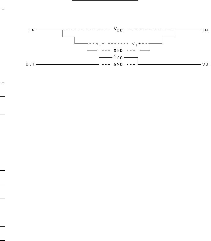
8/ Increment input in 50 mV steps beginning 100 mV below the minimum limit specified until the output changes from VCC to
GND. The input voltage where this transition occurs is VT+.
9/ Decrement input in 50 mV steps beginning 100 mV above the maximum limits specified until the output
changes from GND to VCC. The input voltage where this transition occurs is VT-.
10/ Power dissipation capacitance (CPD) determines the no load dynamic power consumption,
PD = (CPD + CL) (VCC x VCC)f + (ICC x VCC). The dynamic current consumption, IS = (CPD + CL)VCCf + ICC.
For both CPD and IS, f is the frequency of the input signal and d is the duty cycle of the input signal.
11/ This test is for qualification only. Ground bounce tests are performed on a nonswitching (quiescent) output and are used
to measure the magnitude of induced noise caused by other simultaneously switching outputs. The test is performed on
a low noise bench test fixture with all outputs fully dc loaded (IOL maximum and IOH maximum = i.e., 24 mA) and 50 pF of
load capacitance (see figure 3). The loads must be located as close as possible to the device output. Inputs are then
conditioned with 1 MHz pulse (tr = tf = 3.5 1.5 ns) switching simultaneously and in phase such that one output is forced
low and all others (possible) are switched. The low level ground bounce noise is measured at the quiet output using a
F.E.T. oscilloscope probe with at least 1 MΩ impedance. Measurement is taken from the peak of the largest positive
pulse with respect to the nominal low level output voltage (figure 3). The device inputs are then conditioned such that the
output under test is at a high nominal VOH level. The high level ground bounce measurement is then measured from
nominal VOH level to the largest negative peak. This procedure is repeated such that all outputs are tested at a high and
low level with a maximum number of outputs switching.
12/ When using in asynchronous TTL compatible sytems, ground bounce (VGBL and VGBH) = 2000 mV can be a possible
problem.
13/ See EIA/JEDEC STD. No. 78 for electrically induced latch-up test methods and procedures. The values listed for Itrigger
and Vover are to be accurate within 5 percent.
14/ Tests shall be performed in sequence, attributes data only. Functional tests shall include the truth tables and other logic
patterns used for fault detection. Functional tests shall be performed in sequence as approved by the qualifying activity
on qualified devices. H ≥ 2.5 V, L < 2.5 V; high inputs = 3.7 V and low inputs = 0.6 V for VCC = 4.5 V and H ≥ 1.5 V,
L < 1.5 V; high inputs = 2.5 V and low inputs = 0.45 V for VCC = 3.0 V. Tests at VCC = 3.0 V are for RHA specified devices
only (TA = +25C 5C). Functional tests at VCC = 3.0 V are worst case for RHA specified devices.
15/ Device are tested at VCC = 3.0 V and VCC = 4.5 V at TC = +125C for sample testing and at VCC = 3.0 V and VCC = 4.5 V at
TC = +25C for screening. Other voltages of VCC and temperatures are guaranteed, if not tested. See 4.4.1d.
16/ AC limits at VCC = 5.5 V are equal to the limits at VCC = 4.5 V and guaranteed by testing at VCC = 4.5 V. Minimum ac limits
for VCC = 5.5 V are 1.0 ns and guaranteed by guardbanding the VCC = 4.5 V minimum limits to 1.5 ns. For propagation
delay tests, all paths must be tested.
14
|
|
Privacy Statement - Press Release - Copyright Information. - Contact Us |
