 |
|||
|
Page Title:
Figure 3. Switching waveforms and test circuit-cont. |
|
||
| ||||||||||
|
| 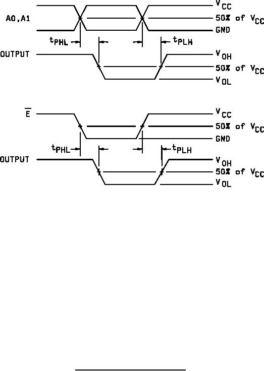 MIL-M-38510/758B
NOTES:
1. CL = 50pF or equivalent (includes test jig and probe capacitance).
2. RL = 500Ω or equivalent.
3. RT = 50Ω or equivalent.
4. Input signal from pulse generator: VIN = 0.0 V to VCC; PRR ≤ 10 MHz; duty cycle = 50 percent, tr ≤ 3.0 ns;
tf ≤ 3.0 ns; tr and tf shall be measured from 10% of VCC to 90% of VCC and from 90% of VCC to 10% of VCC,
respectively.
5. Timing parameters shall be tested at a minimum input frequency of 1 MHz.
FIGURE 3. Switching waveforms and test circuit Continued.
14
|
|
Privacy Statement - Press Release - Copyright Information. - Contact Us |
