 |
|||
|
Page Title:
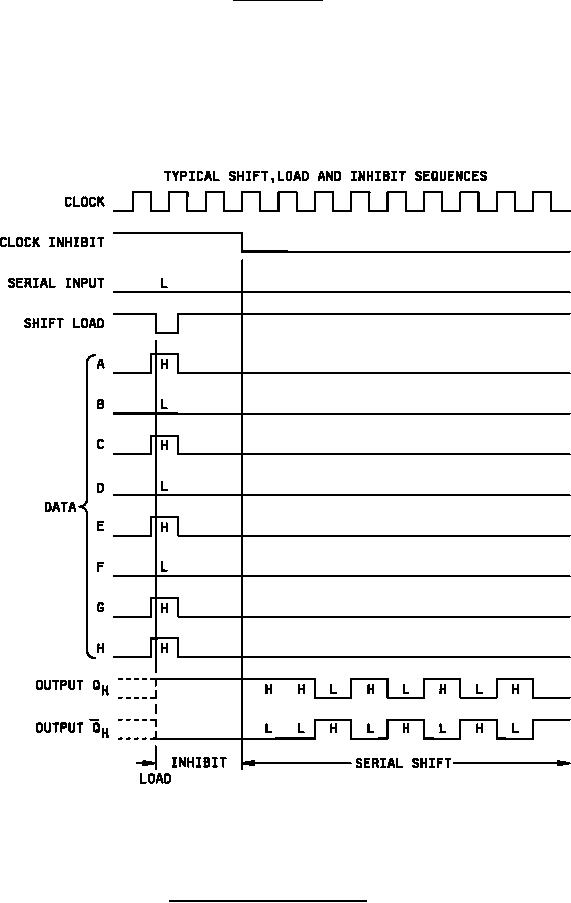
Figure 2. Truth tables and timing diagrams device type 04 |
|
||
| ||||||||||
|
|  MIL-M-38510/9E
Device type 04
Positive logic:
Transfer of information to the output occurs when the clock input goes from a logical L to a logical H.
Clocking is accomplished through a 2 input positive NOR gate, permitting one input to be used as a clock inhibit
function. Holding either of the clock inputs high inhibits clocking, and holding either clock input low with the load input
high enables the other clock input. The clock inhibit should be changed to the high level only while the clock input is
high. Parallel loading is inhibited as long as the load input is high. When taken low, data at the parallel inputs are
loaded directly into the register independently of the state of the clock.
Figure 2. Truth tables and timing diagrams Continued.
19
|
|
Privacy Statement - Press Release - Copyright Information. - Contact Us |
