 |
|||
|
Page Title:
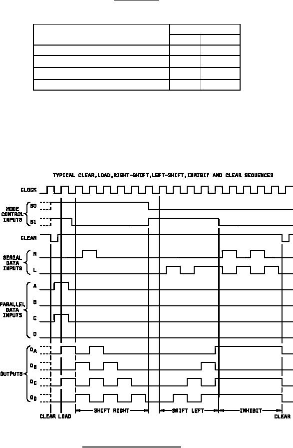
Figure 2. Truth tables and timing diagrams device type 05 |
|
||
| ||||||||||
|
|  MIL-M-38510/9E
Device type 05
Positive logic:
The register has four distinct modes of operation, namely:
MODE CONTROL
S1
S0
Parallel (Broadside) Load
H
H
L
H
Shift Right (in the direction QA toward QD)
H
L
Shift Left (in the direction QD toward QA)
Inhibit Clock (do nothing)
L
L
In the parallel load mode, data is loaded into the associated flip-flop and appears at the output after the positive
transition of the clock input. During loading, serial data flow is inhibited. Shift right is accomplished synchronously
with the rising edge of the clock pulse when S0 is high and S1 is low. Serial data for this mode is entered at the shift
right data input. When S0 is low S1 is high, data shifts left synchronously a new data is entered at the shift left serial
input. Clocking of the flip-flops is inhibited when both mode control inputs are low. The mode controls should be
changed only while the clock input is high.
Figure 2. Truth tables and timing diagrams Continued.
20
|
|
Privacy Statement - Press Release - Copyright Information. - Contact Us |
