 |
|||
|
Page Title:
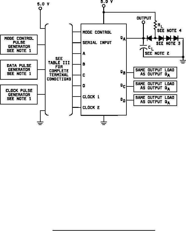
Figure 4. Switching test circuits and waveforms for device type 01. |
|
||
| ||||||||||
|
|  MIL-M-38510/9E
NOTES:
1.
Unless otherwise specified in the notes with the individual waveforms, all pulse generators shall have
the following characteristics: tTLH ≤ 10 ns, tTHL ≤ 10 ns, VIH = 3.0 V minimum, VIL = 0 V, ZOUT = 50 Ω.
2.
CL = 50 pF minimum including jig and probe capacitance.
3.
All diodes are 1N3064 or equivalent.
4.
RL = 400 Ω 5%.
FIGURE 4. Switching test circuits and waveforms for device type 01.
27
|
|
Privacy Statement - Press Release - Copyright Information. - Contact Us |
