 |
|||
|
Page Title:
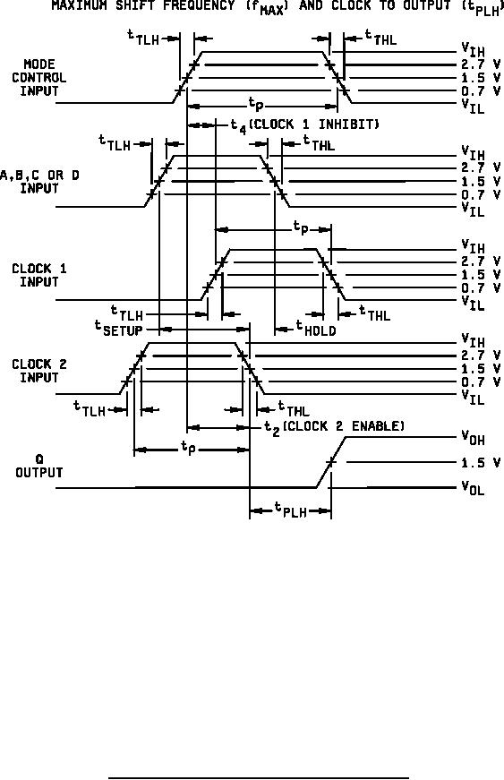
Figure 4. Switching test circuits and waveforms for device type 01-cont. |
|
||
| ||||||||||
|
|  MIL-M-38510/9E
NOTES:
1. Mode control input characteristics: For fMAX, PRR = 22 MHz at TC = 25C and PRR = 16 MHz at -55C ≤
TC ≤ 125C. For tPLH, PRR = 1 MHz, tP = 35 ns, tTLH = tTHL ≤ 10 ns.
2. A, B, C, or D input characteristics: For fMAX, PRR = 11 MHz at TC = 25C and PRR = 8 MHz at -55C ≤ TC
≤ 125C. For tPLH, PRR = 500 kHz, tP = tSETUP + tHOLD. tSETUP = 20 ns, tHOLD = 5 ns, tTLH = tTHL ≤ 10 ns.
3. Clock 1 input characteristics: When testing fMAX, PRR = 11 MHz at 25C and PRR = 8 MHz at -55C ≤ TC
≤ 125C. For tPLH, PRR = 500 kHz, tP = 20 ns minimum, tTLH = tTHL ≤ 10 ns.
4. Clock 2 input characteristics: When testing fMAX, PRR = 22 MHz at 25C and PRR = 16 MHz at -55C ≤
TC ≤ 125C. For tPLH, PRR = 1 MHz, tP = 20 ns minimum, tTLH = tTHL ≤ 10 ns.
5. Serial input = GND.
6. Except for input under test, all other data inputs are open.
FIGURE 4. Switching test circuits and waveforms for device type 01 - Continued.
28
|
|
Privacy Statement - Press Release - Copyright Information. - Contact Us |
