 |
|||
|
Page Title:
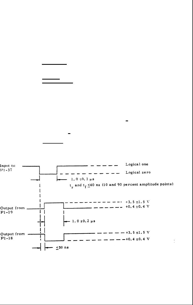
Figure 4. Video Input/Output Signal Waveforms |
|
||
| ||||||||||
|
|  MIL.-M-50747(MU)
8 August 1973
3,3.1.5 Video signal. With the type -A 1 signal shown in figure 4
applied to P1-37, the outputs at Pl-19 and P1-18 shall be as shown on
figure 4. (These signals may be recurring.)
3. 3.1.6 MALF 3 signal.
3. 3.1.6.1 With Logical one type-A and type-A1 signals of table 1
applied to P1-35 and P1-37, respectively, and a momentary logical zero
type-A signal applied to P1- 14, the output at P1-32 shall be +0.20.2V.
With a logical zero type-A signal momentarily applied to P1-33, the
output at P1-32 shall be +3.5 1.OV.
3. 3.1.6.2 With the logical zero type-A signal of table I applied
momentarily to P1- 14, the output at P1-32 shall be +0. 2 + 0.2V. With a
type-A signal applied to P1 -35 and a type-Al signal applied to P1-37 with
the waveforms shown on figure 5 (these signals may be recurring), the
output at P1-32 shall be -3. 5 + 1.0V.
3. 3.1.7 Continuity. With no signals or power applied, direct
continuity (resistance equal to or less than 0.3 ohm), shall exist
between pins P1-7 and P1-12, P1-11 and P1-30, P1-29 and P1-31, and
between P1-29 and P1-13.
Figure 4. Video Input/Output Signal Waveforms
7
|
|
Privacy Statement - Press Release - Copyright Information. - Contact Us |
