 |
|||
|
Page Title:
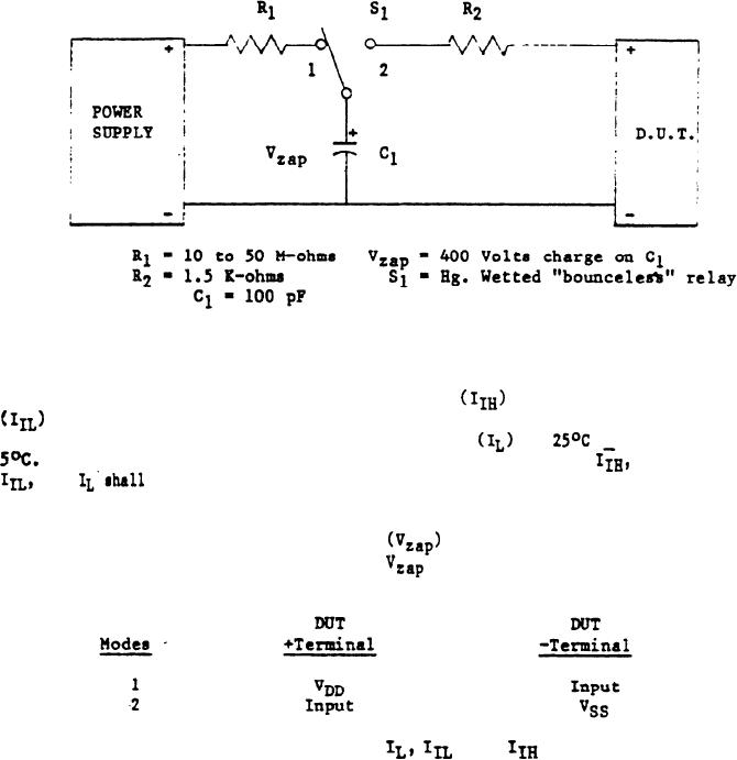
Figure 2. Static discharge test circuit. |
|
||
| ||||||||||
|
|  MIL-M-63324A(AR)
FIGURE 2.
Static discharge test circuit.
a. Measure input current, high level
and low level
25C + 5C at one input terminal of device under test
at
+
(DUT). Also measure quiescent device current
The test limit for a single terminal measurement of
and
shall be increased a maximum of 10% of their value
specified in the electrical characteristic Table I.
b. Apply the static discharge
to the DUT in each of
the following modes by charging Cl to
with S1 in position 1
and then switching to position 2.
c. Within 24 hours repeat the
and
measurements on the same terminals as performed above. If the DUT
exhibits leakage currents in excess of-the specified test limit (see
"a" above) at this time, it shall be classed defective.
(Destructive test).
4.5.4 Data requirements. The contractor shall submit a quality
inspection test, demonstration and evaluation report giving all
detailed inspection and test results in accordance with Data Item
Description DI-R-1724. Test report shall be submitted to the
technical agency listed in 6.5.
14
|
|
Privacy Statement - Press Release - Copyright Information. - Contact Us |
