 |
|||
|
Page Title:
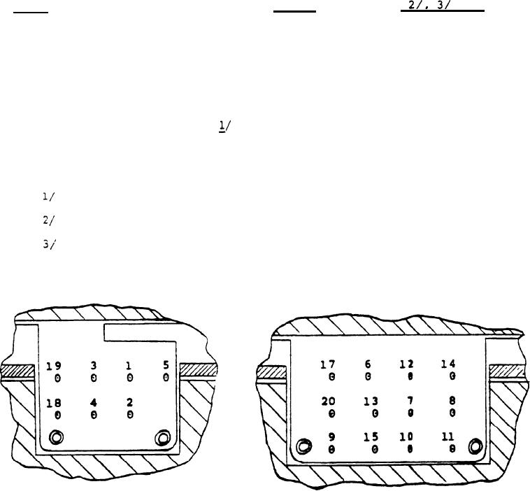
Table 2. Body Assembly Electrical Checks Prior to Loading |
|
||
| ||||||||||
|
|  MIL-M-63456A(AR)
TABLE II
Body Assembly Electrical Checks
Prior to Loading
Requirements
Test
Electrical
Points
Check
0.2 - 0.7 ohms
13-8
1.
Short Across Firng Capacitor
18-8
0.005 volts
2.
inactivated Battery
max x
10 - 18
3.
3 -8
6.0 ohms max
4* Tripline Resistance (1$7)
6.0 ohms max
4-8
5. Tripline Resistance (2&6)
6.0 ohms max
1-8
6. Tripline Resistance (3&8)
6.0 ohms max
2 -8
7. Tripline Resistance (4&5)
0.85 - 1.4
5 -8
8. Receiver Coil Resistance
ohms
2.0 - 6.0 ohms
19-8
9. Pressure Cartridge Resistance
4.0 - 9.5 ohms
20-8
10. Piston Actuator Resistance
3.0 - 7.5 ohms
17-8
11. Detonator Resistance
The Receiver Coil is in para;;e; with a series connected
shorting bar and Electric Battery Primer.
For voltage ckecks, use a voltmeter with a 10 megohm input
impedance.
For resistance checks, use a milliohmmeter having a short
circuit current of 1 ma or less e.g. Valhalla or equivalent.
(Dwg. . 92927 13)
TEST POINT LAYOUT
16
|
|
Privacy Statement - Press Release - Copyright Information. - Contact Us |