 |
|||
|
Page Title:
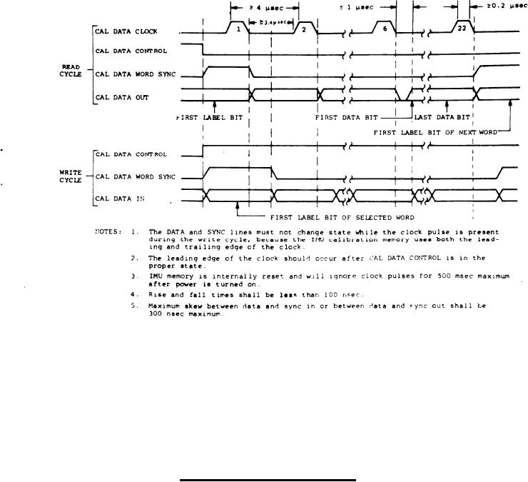
Figure 9. ANCU/IMU Calibration Data Timing Diagram |
|
||
| ||||||||||
|
|  MIL-N-81604C(AS)
ANCU/IMU Calibration Data Timing Diagram
Figure 9.
Para 3.4.4.1f(1)
(cont)
shall supply a 250-KHz clock with a pulse width
of 500 nanoseconds. The line driver in the
ANCU and the line receiver in the IMU shall be
Type A circuits.
Calibration Data Control - The true (low, open,
(2)
or ANCU power off) state of this discrete shall
be supplied to the IMU to place the IMU cali-
bration memory in a "read" state, thus allowing
calibration memory data to be transmitted from
the IMU. The false state of this discrete
shall be supplied to the IMU from the ANCU or
7
test equipment designed in accordance with
45
|
|
Privacy Statement - Press Release - Copyright Information. - Contact Us |
