 |
|||
|
|
|||
| ||||||||||
|
|  MIL-N-85005A(AS)
RADAR - The Converter shall include an alternate
3.5.5.5.3
action PBI providing radar mode control. The PBI shall be normally
illuminated green, shall be amber when activated, and shall be non-
illuminated and non-programmable when the APS-80 is not operating. When
actuated green to amber, the PBI shall enable the radar sweeps and video
and generate the RADAR ON function code in the command word. When
depressed amber to green it shall disable the radar sweeps and video and
generate the RADAR OFF function code in the command word. The radar
mode shall be inhibited when on the 256, 512, and 1024 mile scales.
When in the radar mode and scaling is changed to 256 miles or more,
radar shall automatically be removed from the IP-886B/ASA-66 display,
the RADAR OFF function code generated, and the PBI returned to green.
Markers shall not be deleted as a function of the Radar Mode.
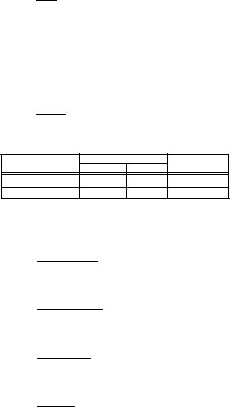
GEO/TAC - This shall be
an alternate action PBI.
3.5.5.5.4
The illumination shall change from green to
amber for the function
selected. The PBI shall control a discrete
line pair at the computer
interface, the discrete state corresponding
to the illumination state of
the PBI as follows:
Illumination
Discrete
PBI State
TAC
GEO
True
Green
Amber
GEO
False
Amber
Green
TAC
The switch illumination shall be set to GEO (amber) and TAC (green) when
ITADS power is turned on and thereafter shall be an alternating function
of switch action. The PBI shall have an opaque field with illuminated
dual legend.
Radar Intensity - This control shall be a continu-
3.5.5.5.5
ously variable knob which shall increase the brightness of the radar
video when rotated in the clockwise direction. It shall not be possible
to rotate this control in the counter-clockwise direction such that
nominal radar video is not visible on the display.
Marker Intensity - This continuously variable
3.5.5.5.6
control shall increase the intensity of the markers and associated lines
and circles when rotated in the clockwise direction. With the control
in the full counterclockwise position, the markers shall still be dimly
visible.
LED Intensity - This continuously variable control
3.5.5.5.7
shall increase the intensity of illumination of the LED displays on the
Converter and the TDC when rotated in the clockwise direction. With the
control in the full CCW position, all commanded segments of the nominally
illuminated LED displays shall still be dimly visible.
RADAR CAL - This continuously variable control shall
3.5.5.5.8
be a push-to-turn type and shall adjust the start time of the radar
sweep for accurate calibration between the radar video and radar display
deflection.
- 82 -
|
|
Privacy Statement - Press Release - Copyright Information. - Contact Us |