 |
|||
|
|
|||
| ||||||||||
|
|  MIL-O-81148(OS)
4.4.4.4.2 Repeat 4.4.4.4.1 for each remaining pin (pins 2, 3, 6, and
7) of the oscillator.
4.4.4.5 DC resistance as set forth in 3.4.1.2:
4.4.4.5.1 Calibrate the resistance bridge to measure resistance in
accordance with the instruction provided with that instrument.
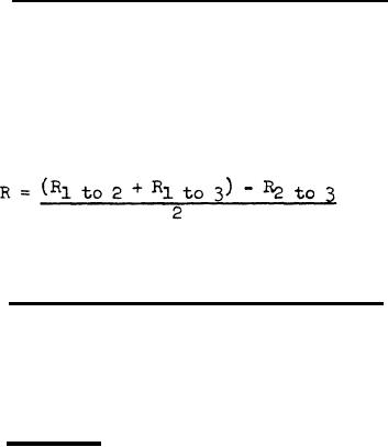
4.4.4.5.2 Measure the resistances from pins 1 to 2, 1 to 3, and 2 to
3 of the oscillator. Compute the value of the resistance between the coil
center tap and pin 1 by the expression
This resistance shall be 1800 ohms, plus or minus 1 percent.
resistance as set forth in 3.4.1.3.:
4.4.k.6
DC
4.4.4.6.1 Measure the resistance from pin 2 to pin 7 of the oscil-
lator. This resistance shall be 330,000 ohms, plus or minus 5 percent.
4.4.4.6.2 Remove the resistance bridge test leads.
4.4.4.7 Frequency. To measure the frequency as set forth in 3.4.2:
4.4.4.7.1 Remove power from the power suppply. Connect the oscillator
test circuit as shown in Figure 1. Place the 6C4WA tube properly in its
socket, and remove the oscillator from its socket. Check the test cir-
cuit wiring capacitances between pins 1, 2, 6, and 7 of the oscillator
socket and ground to ensure that they are in accordance with 4.4.3.18.
4.4.4.7.2 Replace the oscillator in its socket and apply power to the
power supply and test circuit, allowing enough warmup time for the equip-
ment to stabilize.
4.4.4.7.3 Check the calibration Of the electronic counter in accord-
ante with the instructions provided with that instrument. when the
counter has been satisfactorily checked, set the controls to measure
frequency.
4.4.4.7.4 Connect the counter imput as shown in Figure 1. Read and
record the frequenc y indicated on the counter. This frequency shall be
54,040 plus or minus 50 Hz.
4.4.4. 7. 5 Attach the ground clip to pin 6 of the oscillator socket.
Read and record the frequency y Indicated on the counter. This frequency
shall be 51,540 plus or minus 50 Hz.
11
|
|
Privacy Statement - Press Release - Copyright Information. - Contact Us |
