 |
|||
|
Page Title:
Mechanical soundness and capacity test |
|
||
| ||||||||||
|
|  MIL-P-18682D(SH)
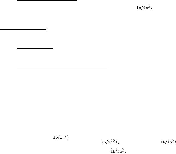
4.6.1 Hydrostatic pressure test. All pressure boundary parts shall be
tested hydrostatically to a pressure one and one-half times the maximum discharge
pressure at maximum submergence, but in no case less than 50
The hydro-
static test pressure shall be maintained for at least 30 minutes or longer as
necessary for examination of entire casing.
Acceptance criteria: The pump shall exhibit no leakage through the pressure
boundary material or joints. The leaking rate through a mechanical seal shall
not exceed 5 drops per minute.
4.6.2 Over-speed test. Each variable speed driver capable of overspeeding
shall be over-speed tested in accordance with the specification applicable to the
driver.
4.6.3 Mechanical soundness and capacity test. This test shall be conducted,
recorded, and reported in accordance with the centrifugal pump Rating Standard
and Test Code of the Hydraulic Institute, to the extent that these standards are
applicable and are not in conflict with the requirements specified herein. The
test report for each pump shall include the following as a minimum: (a) identi-
fication of the major pump components (pump, gear assembly, driver) by manufac-
turer's drawing number and serial number that were tested; (b) identification of
the diameter of the impeller(s) tested in the pump; (c) a dimensioned sketch of
the test loop showing location of the pump, location of all instrumentation,
distance (vertical and along the pipe axis) from the suction and discharge gage
taps to the pump suction and discharge flanges, vertical distance from the gage(s)
to the elevation datum to which they are calibrated, azimuthal location of the
gage taps on the pipe circumference, and location and orientation of any elbows
in the pump suction piping; (d) the test loop water temperature during the test;
(e) a list of the test instruments including date of last calibration, advertised
accuracy, size (e.g., 0.25
of the smallest graduation on the readout
scale, range of the readout scale (e.g., 0-100
and unit (e.g.,
of measurement including the water temperature the gages are calibrated for if a
gage is calibrated in feet of water rather than in
(f) the data sheets
of all recorded data, with the unit of measurement identified for all data;
(g) a sample calculation of each type of calculation converting the raw data to
specified conditions and showing the conversion in sufficient detail to permit
an independent reviewer to verify the calculations, including all temperature
and density corrections; (h) a COPY of the specific table of water properties
used in the calculations and a reference to the source of that table; and (i) a
plot of the measured head-capacity curve, corrected to the specified operating
conditions following the method described in the sample calculations. The test
shall be performed as follows:
(a)
Operate the pump and its driver, if motor driven, continuously
at the maximum rated speed and capacity, with the pumped fluid
at ambient temperature until bearing temperatures (not including
water-lubricated bearings) stabilize. Stabilization is defined
as three consecutively recorded readings taken over intervals of
at least 15 minutes that fall within 3F band when adjusted for
ambient. The three consecutive readings shall not be constantly
rising. The pump operation shall be monitored for proper
functioning of safety devices, bearing lubrication, and for
smooth running.
37
|
|
Privacy Statement - Press Release - Copyright Information. - Contact Us |