 |
|||
|
Page Title:
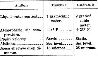
Table I. Ice control design conditions |
|
||
| ||||||||||
|
|  MIL-P-26366A
ous operation of the ice control system in flight
sient conditions of normal engine operation and
shall not damage the propeller system. Re-
within the Aq level specified in the model speci-
quirements for indication of the operation of
fication. Restrictions in propeller operating
the ice control system shall be specified in the
conditions determined by vibration surveys shall
model specification.
be listed in the model specification.
3.20.2 Electrical ice control system.
3 . 1 9 Propeller accessory limiting tem-
p e r a t u r e s . Engine and engine compartment
3.20.2.1 Electrical contact surface. All alu-
mounted propeller accessories shall be capable
minum-oxide films, lacquers, or similar noncon-
of continuous operation under normal operat-
ducting coatings shall be removed from the ac-
ing conditions and under the maximum temper-
tual contact area of all surfaces required to act
ature conditions anticipated in their environ-
as a path for electrical power and from the local
ment. Airframe mounted propeller accessories
areas under screws, nuts, or the like used for
other than the above shall be designed to meet
assembly or mounting purposes to provide an
the ambient temperature limitations of Specifi-
electrical connection in accordance with the re-
cation MIL-E-5272. Maximum temperatures
quirements of Specification MIL-W-5088.
of the environment and the accessories, heat re-
3.20.22 Electrical ice control circuits. All
jection rates, maximum endurance times and
electrical circuits pertaining to ice control sys-
maximum temperatures after shutdown, as ap-
tems shall be so physically and electrically iso-
p l i c a b l e , shall be specified in the model
lated that no interference with the propeller
specification.
operation or control will result. The leads used
3 . 2 0 Ice control system. The propeller
to conduct electrical power to the heating ele-
shall incorporate an ice control system for the
ments shall withstand the aerodynamic centrif-
blades, cuffs, and spinner. Either electrical,
ugal and vibratory loading to which they will
fluid, gas, compound, or mechanical ice control
be subjected during propeller operation.
systems or combinations of two or more of
3.20.2.3 Bonding materials. Cements, ad-
such systems may be used when approved
hesives, or brazing used to bond blade, spinner,
by the procuring activity. The ice control sys-
or cuff electrical heating elements shall be spec-
tem(s) shall be specified in the model specifica-
ified in the model specification. Bonding
tion. The propeller shall operate satisfactorily
processes which cause a reduction in physical
under the meteorological conditions included in
properties of the item to which the element is
table I.
b o n d e d shall be specified in the model
T ABLE I. Ice control design conditions
specification.
3.20.2.4 Cover surfaces. Surfaces exposed
to the air blast shall consist only of materials
designed to resist abrasion and corrosion. Ex-
ternal surfaces of installed heating elements
shall be aerodynamically smooth. Externally
mounted rubber or plastic surfaced elements
shall be inherently of sufficient flexibility and
elasticity to allow installation in service areas
without special dies, stretching equipment., etc.
3.20.2.5 Blade heating area. The heating
elements shall heat the inboard section of the
3.20.1 Type of ice control. The type of ice
exposed blade length to the propeller radius ap-
control may be continuous, cyclic, or a combina-
proved by the procuring activity. The width
tion of both as specified in the model specifica-
of the blade heated on both the thrust and cam-
tion. Unless continuous ice control is provided,
ber frees shall extend from the leading edge
operation of the ice control system shall be ac-
back to a distance at no point less than 17
complished either automatically or manually as
percent of the blade chord.
specked in the model specification. Continu-
7
|
|
Privacy Statement - Press Release - Copyright Information. - Contact Us |
