 |
|||
|
Page Title:
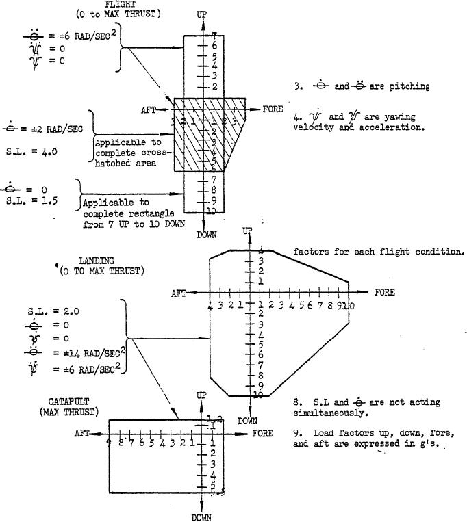
Figure 2. Flight maneuver load diagrams. |
|
||
| ||||||||||
|
|  MIL-P-26366A
ing provisions shall be provided on the propeller
3.15 Overall dimensions. The maximum
for support. of the propeller on ground equip-
overall dimensions of the propeller shall be
ment. The location and dimensions shall be
shown on the installation drawing.
shown on the installation drawing.
3 . 1 6 Flight maneuver forces. The pro-
3.18 Rotating parts.
peller shall withstand without permanent de-
3.18.1 Vibration. The propeller shall be
formation or failure the conditions specified in
free of destructive vibration at the rated propel-
figure 2.
ler conditions including steady-state and tran-
3.17 Ground support attachments. Mount-
1. Load factors and angular
v e l o c i t i e s and accelerations
should be taken at or about
the C.G. of the engine.
2 . Side load factors (S.L.)
a c t to either side.
v e l o c i t y and acceleration.
5. Down loads occur during
pull out or up gust.
6. Fore loads occur during
a r r e s t e d landing.
7. Propeller aerodynamic (IXP)
moments and propeller side forces
for each application must be
considered in combination with load
Figure 2. Flight maneuver load diagrams.
6
|
|
Privacy Statement - Press Release - Copyright Information. - Contact Us |