 |
|||
|
Page Title:
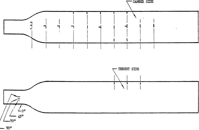
Figure 5. Typical strain gage layout. |
|
||
| ||||||||||
|
|  MIL-P-26366A
the number of strain gages and types of each
Ambient temperature, F.*
used, their distribution, the range of operat-
Established formula for determining cor-
ing conditions over which vibratory stress data
rected horsepower, thrust, and torque.
will be recorded, the type of recording equip-
Data for reading oscillograph recordings
ment used and the intervals at which record-
of stress traces.
ings will be made, and the propeller com-
*Note. Ambient temperature shall be recorded
ponents to be subjected to the vibratory
at intervals not greater than 60 minutes.
stress survey shall be subject to review and
4.5.1.2 Teardown inspection. The propeller
approval by the procuring activity. Addi-
submitted for test shall be completely disas-
tional or revised instrumentation similar in
sembled to allow a detailed inspection of all
nature is permitted. The instrumentation shall
vital working parts. Those components which
be sufficient to record stress traces, propeller
are permanently joined together will be ex-
rpm, and blade angle. The following is pro-
cepted. Individual parts or components shall
vided as a guide for the survey. Strain gages
be examined for evidence of suitable quality of
shall be installed on one blade of the propeller
materials based on physical inspections and
substantially in accordance with figure 5 for
process control data and may be supplemented
measurement of blade shank longitudinal bend-
by physical and chemical tests to determine the
ing and transverse stresses. A limited number
extent of conformance to contractor's specifica-
of strain gages shall be installed on adjacent or
tions and drawings. The condition of the in-
opposite or both adjacent and opposite propeller
dividual parts or components shall be recorded.
blades, as required. Instrumentation data for-
Periodic inspection during tests will be ap-
mat for strain, gage installation on the propeller
proved by the procuring activity.
blade and their respective connection to the re-
4.5.1.3 Instrumentation. The instrumenta-
cording oscillograph used f or making the vibra-
tion and techniques used for recording the
tory stress data shall be prepared substantially
in accordance with figures 6 and 7.
vibratory stress survey of the whirl stand tests.
F IGURE 5. Typical strain gage layout.
20
|
|
Privacy Statement - Press Release - Copyright Information. - Contact Us |
