 |
|||
|
|
|||
| ||||||||||
|
|  MIL-P-27431B(USAF)
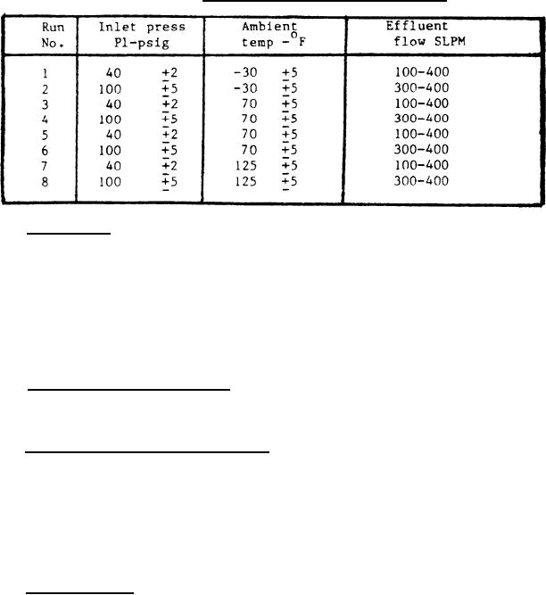
e. An effluent flow rate outside the ranges indicated In Table I
in SLPM.
f. Failure of heater indicator light to cycle on an off coincident
with application and removal of power at the heating element.
TABLE I.
Performance test (long method).
4.6.6 Drop test. The complete purging kit with case, shall be raised to a
height of 5 feet above a concrete surface and dropped in such manner that one corner
of the case squarely contacts the concrete surface. The test shall be repeated by
dropping the unit on the corner diametrically opposite to the corner that originally
contracted the surface. The unit shall then be opened and examined. If any of the
unit components have come loose from their retaining clips or fasteners, or if any of
the components other than the carrying case have been damaged, or if the carrying
case is incapable of containing and restraining the contents, the unit shall be
rejected.
4.6.7 Explosion proofing test. The heat exchanger assembly shall be subjected
to explosion proofing in accordance with Procedure I of MIL-STD 810 to determine
compliance with 3.5.7.
4.6.8 Heat exchanger endurance test. The heat exchanger assembly power cable
shall be connected to a source of 115 5V, 60 or 400 cycle power and the toggle
switch turned on. Air, oxygen} or nitrogen at any suitable pressure shall be
intermittently applied to the heat exchanger inlet causing the thermostatic controls
to cycle the heater on and off as in normal operation but with a greater than normal
frequency of cycling. The heat exchanger assembly shall be operated in this manner
for at least 60,000 on-off cycles of the thermostatic controls, after which the
assembly shall be subjected to the test specified in 4.6.6.
4.6.9 No flow test. The purging unit components shall be assembled and
instrumented as shown on Figure 3. Clean, dry, oxygen at 500 5 psig, shall be
applied to the heat exchanger inlet, 115 5V, 60 or 400 cycle single phase power
shall be applied to the power cable and the toggle switch turned on. The unit shall
be operated for 20 minutes at rated conditions to establish stabilization. The time
required for the heating element to reach thermostatic cutoff temperature shall be
recorded. With pressure still applied to the heat exchanger inlet, with power
supplied to the unit and the toggle switch remaining in the on position, the flow
shall be shut off downstream from the filler valve for 8 hours. Evidence of damage,
malfunction or overheating shall constitute test failure and cause for rejection.
12
|
|
Privacy Statement - Press Release - Copyright Information. - Contact Us |
