 |
|||
|
|
|||
| ||||||||||
|
|  MIL-P-63332(AR)
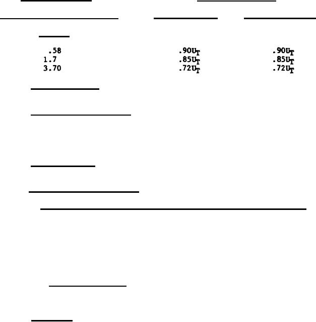
ANGULAR SPACING
CONTRAST TRANSFER
Vertical lines
Horizontal lines
(in line pairs/milllradian)
On-axis
3.11.5 Luminance gain.
The luminance gain shall be not less than 525
foot lamberts
3.11.6 Stray light luminance. This requirement shall be met with the
periscope set for infinity focus. Stray light luminance contribution over the
image of a black disk, subtending a solid angle equal to the field of view; in
a white surround, subtending a solid angle of not less than 120 degrees, shall
not exceed 20 percent.
3.11.7 Field of view.
The field of view shall be not less than 90 milli-
radians.
3.11.8 Protected reticle pattern.
3.11.8.1 Definition and visibility, clear, mediun and dark filters. The
image of the reticle pattern shall be well defined and clearly visible when
viewed with the unaided eye under the following conditions:
a. The entrance window covered to prevent entrance of light using
the clear and medium filter positions.
b. The periscope viewing an evenly illuminated field of not less
than 10 foot lamberts luminance with the filter wheel in the dark position.
3.3.11.8.2 Reticle accuracy. The angular value between the boresight
cross and the maximum range graduation of the projected reticle pattern shall
be within 2.0 percent of the value specified on the reticle drawing.
3.11.9 Accuracy. Unless otherwise specified the requirements of
3.11.9.1.1 through 3.11.9.1.2, 3.11.9.2 through 3.11.9.5.3 and 3.11.9.7
through 3.11.9.8.4 shall be met with:
a. The conditions of 3.11a, 3.11b, 3.11c and 3.11d.
b. Datum Plane "A" defined as Datum Plane "A" shown on Drawing
F11834835, horizontal.
c. A plane defined by the two pads on Mount Assembly 11834835 (for
the purpose of these requirements referred to as Datum Plane "D") perpendi-
cular.
d. Surface "C" of the input coupling, shown on Drawing F105422O4,
positioned 67 degrees 30 minutes with respect to Datum Plane "A" as measured
in a plane perpendicular to Datum Planes "A" and "D".
e. Elevation defined as the direction of line of sight deviation
which occurs when the angular value defined in 3.11.9d is increased.
8
|
|
Privacy Statement - Press Release - Copyright Information. - Contact Us |
