 |
|||
|
Page Title:
Circuit board assembly test procedure |
|
||
| ||||||||||
|
|  MIL-P-70624A(AR)
4.5.2.6 Circuit board assembly test procedure.
a. Remove voltmeter and generator. Reset oscilloscope
common to Pin K and vertical input to Y; set up scope for positive
trigger. V input, 5 v/cm and Time, 1 millisec/cm.
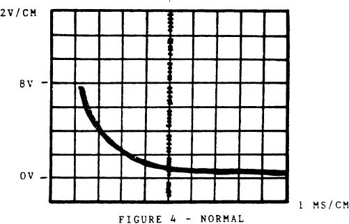
b. Activate S3 switch. Pin E should read 13 1V the first
6 to 10 seconds and after that less than 1 volt. Scope reading
should be 33 3 volts peak decaying to O volts over 6 milliseconds
(Figure 5) .
It should read less than 1 volt.
Recheck Pin U.
c.
Pin U should read 13 1 Volt.
Press S2 switch.
d.
Connect generator and voltmeter. Readjust signal
generator to 1200 HZ: Activate S3 switch momentarily. Pin E should
read 13 1 volts and Pin U less than 1 volt. press S2 switch; Pin
U should read 13 1 volts.
f. Turn off all power and disconnect board, equipment and
the lead "U108-1".
83
|
|
Privacy Statement - Press Release - Copyright Information. - Contact Us |
