 |
|||
|
Page Title:
Circuit board assembly test procedure |
|
||
| ||||||||||
|
|  MIL-P-70624A(AR)
4.5.3 Printed circuit board assembly (Dwg. 9360013) test
procedure.
4.5.3.1 Circuit board assembly test procedure.
Set a power supply to 26 .5 VDC.
a.
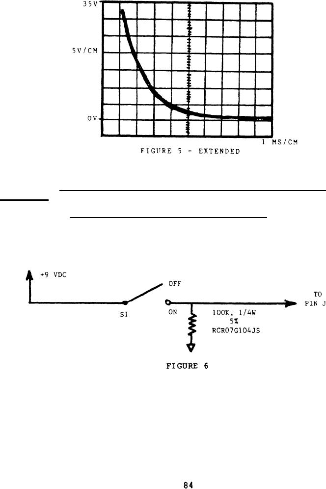
Apply Figure 6 to the board.
b.
c. Apply 26 .5 VDC to pins F (+) and A, P (-) and 8.0
.5 VDC to pin S (+) and A, P (-). Using a multimeter, measure the
pin values for the requirements specified in 3.5.1.
|
|
Privacy Statement - Press Release - Copyright Information. - Contact Us |
