 |
|||
|
|
|||
| ||||||||||
|
|  MIL-P-82436 (OS)
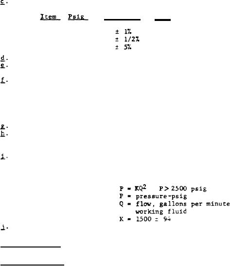
Gages:
Accuracy
Size
Range
Full Scale
Dia.
A
0-1250
6 in.
B
0-5000
6 in.
C
4 in.
0-25
Relief valve:
Cracking pressure, 4500 100 psig
Accumulator:
Size, 10 cubic inches; test pressure 8000
psig minimum
Working fluid supply: Capable of supplying to the pump
a 5 percent solution, by weight,
of water-soluble oil in water at
a rate of 2 gpm at 7 3 psig and
at any temperature between +32
and +98 F
Drive unit: 5 horsepower synchronous electric, nominal
Outlet filter: 25 micron maximum, 5 square inches of screen
area minimum, 4000 psig minimum working
pressure
Orifice, flow-limiting:
The fixed orifice, when connected
in the test set-up, Figure 3,
shall produce a flow rate as de-
fined by:
Inlet filter:
50 to 80 micron
4. 5.4
Test procedures.
4.5.4.1
Operational test.
The pump, containing twenty cubic centi-
meters of oil, see 6.7, shall be mounted in the test stand and connected
the auxiliary equipment. Prior to testing, the flow rate shall be preset
to
as folows: remove the Adjusting Screw Nut (Figure 1), apply a pressure Of
300 10 psig to the bias port. With the pump being driven at 3880 10
rpm, set the inlet pressure to 7 3 psig. Position the Valve Adjusting
Screw (Figure I) to obtain an outlet pressure of 2775 10 psig. Replace
the Adjusting Screw Nut and secure with a lockwire. The pump shall be
operated in accordance with the sequence indicated in Table XI. The pump
shall deliver the working fluid at the pressures specified in Table XI,
when the pump is driven at 3880 10 rpm, bias pressure is controlled within
the respective parameters and the inlet pressure in maintained between 4
and 10 psig. The orifice shall not be by-passed thus unloading the pump
during the test.
18
|
|
Privacy Statement - Press Release - Copyright Information. - Contact Us |
