 |
|||
|
Page Title:
Figure 1. 1. Dimensions and configurations - Continued |
|
||
| ||||||||||
|
|  MIL-R-39016/32F
Inches
mm
Inches
mm
Inches
mm
Inches
mm
Inches
mm
.002
0.05
.030
0.76
.150
3.81
.375
9.52
.800
20.32
.003
0.08
.031
0.79
.187
4.75
.400
10.16
.875
22.22
.005
0.13
.062
1.57
.192
4.88
.460
11.68
1.062
26.97
.010
0.25
.100
2.54
.200
5.08
.462
11.73
1.340
34.04
.015
0.38
.112
2.84
.210
5.33
.488
12.40
1.390
35.31
.020
0.51
.120
3.05
.220
5.59
.600
15.24
.025
0.64
.136
3.45
.281
7.14
.603
15.32
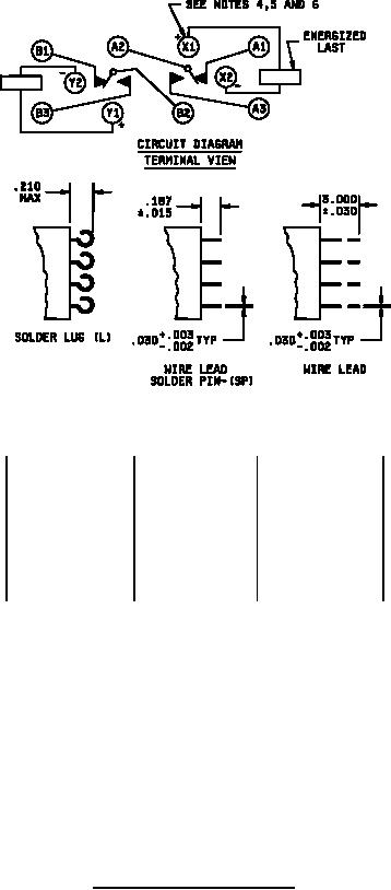
NOTES:
1. Dimensions are in inches.
2. Unless otherwise specified, tolerance is .010 (0.25 mm).
3. Metric equivalents are given for general information only.
4. Terminal indicated shall be identified by a contrasting bead. Relays shall have plus (+) and minus (-)
signs placed on the circuit diagram as shown above.
5. Energizing the indicated coil with the indicated polarity and voltage shall cause the relay contacts to
assume the position shown.
6. When relay enclosure has side mounting hardware, the contrasting header bead shall be located on the
same side as the mounting hardware (bracket mount and stud mount).
7. Coil symbol optional in accordance with MIL-STD-1285.
8. Terminal numbers in circuit diagram are for reference only. Numbers do not appear on relay.
FIGURE 1. Dimensions and configurations - Continued.
2
|
|
Privacy Statement - Press Release - Copyright Information. - Contact Us |
