 |
|||
|
|
|||
| ||||||||||
|
|  MIL-R-50263A (PA)
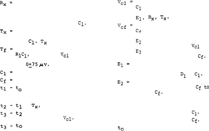
Voltage level to which
Time setting resistor which
(timing) is charged
sets the range by fixing the
under fixed conditions:
rate of charge during `I'X,
thus fixes the amount of
charge available to
Voltage level to which
is charged from a
Fixed time during which the
negative voltage supply
positive charge is applied
until a comparator
(nominal) 0.2%.
to
senses that Vcf =
-
Time delay to function or time,
is satisfied and stops
it takes
to discharge
further charging of
from its initial set voltage
Is a constant current pos-
to
itive voltage supply
Timing Capacitor
applied across
+
Firing & Power Supply Capacitor
Negative D.C. power supply
applied across D2 +
= time delay to allow switch-
charge
ing contacts bounce to
subside.
E3 = Fixed regulated reference
voltage.
=
see above and Fig. 1.
=
Time to charge Cf - Depends D1 = Steering Diode for
on E3 and
D2 = Steering Diode for
= Total time allowed to
= Time when setter receives
charge fuze.
signal to start its cycle
for charging an RC Fuze.
Fuze Signature = Voltage vs time
description at
input to round
during setting
of fuze.
4. The fuze charge cable from setter to fuze, assembled to round and
mounted in launcher, must meet electromagnetic interference suscep-
tibility requirements of MIL-STD-461, -462 (Cs01, Cs02, Cs06). Mon-
itoring of fuze for timing circuitry shall be accomplished by in-
serting a "T" connector between the fuze umbilical and launcher
adapter and making measurements directly across charge line and
ground. Induced voltage shall not be greater than 0.3 volt peak.
The design shall incorporate circuit elements to eliminate or reduce
to tolerable levels effects from electromagnetic radiation or elect-
rical impulse pickup.
5. The setter shall contain a fuze panel with precision range setting
resistors (Rx) and switches for the selection of desired Canopy
Height or Range To Target in the respective Canopy Mode (XM433E1)
and Airburst Range Mode (M439 Fuze) indicated in Table 1.
6. Input power shall be 115 10 volts @ 60 5Hz. Internal reg-
ulated power supplies shall use the same power source. All of the
following cables shall be 80 (eighty) feet long: 115V 60 Hz power
cable to setter; remote control; scope sync and buffered fuze charge
signature signal cables to setter; 28 VDC fire power source cable to
setter. The fuze charge coaxial cable and the D.C. fire signal cable
from setter to sequencer and fire box shall be 6 (six) feet long. The
portable case and chassis shall be earth grounded.
37
|
|
Privacy Statement - Press Release - Copyright Information. - Contact Us |