 |
|||
|
Page Title:
Manual control cable subassembly had transmission |
|
||
| ||||||||||
|
|  MIL-R-8236F
subassemblies of these types. The manual control cable subassembly shall be operated, without any degradation of
performance (manual and automatic modes), by all manual control. handle subassemblies of that type approved for
QPL. The manual control cable subassemblies shall meet the requirements of Figures 12 through 15, as applicable
for each type of inertia reel configuration (see 4.4.3.4.3).
3.4.3.4.4 Manual control cable subassembly had transmission. The manual control cable subassembly shall
be capable of transmitting manual control handle loads required to actuate the inertia reel locking mechanism
when the cable or webbing lead-in strap, as applicable, is tensioned with a 25 pound load (see 4.4.3.4.4).
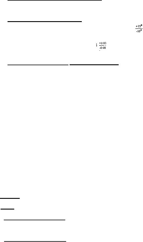
3.4.3.4.5 Manual control cable subassembly throw. The MA-2 type manual control cable subassembly shall
be capable of receiving and delivering a 0.38 0.03 inch throw (stroke) through a 50
throw angle of the
MA-2 type manual control handle subassembly. The MA-6, MA-8, MA- 14, and MA- 16 type manual control cable
inch throw (stroke) through a 50 10
subassemblies shall be capable of receiving and delivering a 0.68
throw angle of the MA-6, MA-S, MA-14, and MA-16 type manual control handle subassembly (see 4.4.3.4.5).
3.4.3.4.6 Manual control cable subassembly performance recquirements. The manual control cable
subassembly shall meet the material, design and performance requirements:
a. Dimensions (see Figures 12-15).
b. Materials (see 3.3).
c. Design and construction (see 3.4).
d. Manual control cable subassembly design requirements (see 3.4.3.4).
e. Cable throw (stroke) (see 3.4.3.4.1, 3.4.3.4.5).
f. Adjustability (see 3.4.3.4.2).
g. Interchangeability (see 3.4.3.4.3).
h. Load transmission (see 3.4.3.4.4).
i. Environmental (see 3.5.5).
j. Life cycle (see 3.5.6.3).
k. Workmanship (see 3.8).
3.4.4 Dimensions. The inertia reel dimensions shall conform to Figures 1 through 15, as applicable.
3.4.5 Weight.
3.4.5.1 Weight of MA-1 type inertia reel. The maximum weight for the MA-1 type of inertia reel, including
the shoulder harness lead-in cable. but excluding the manual control cable and manual control handle
subassemblies, shall be 3.5 pounds.
3.4.5.2 Weight of MA-2 type inertia reel. The maximum weight for the MA-2 type of inertia red, including
the shoulder harness lead-in cable, but excluding the manual control cable and manual control handle
subassemblies, shall be 4 pounds.
9
|
|
Privacy Statement - Press Release - Copyright Information. - Contact Us |
