 |
|||
|
Page Title:
Resistance to soldering heat (see 3.22) |
|
||
| ||||||||||
|
|  MIL-R-83407B
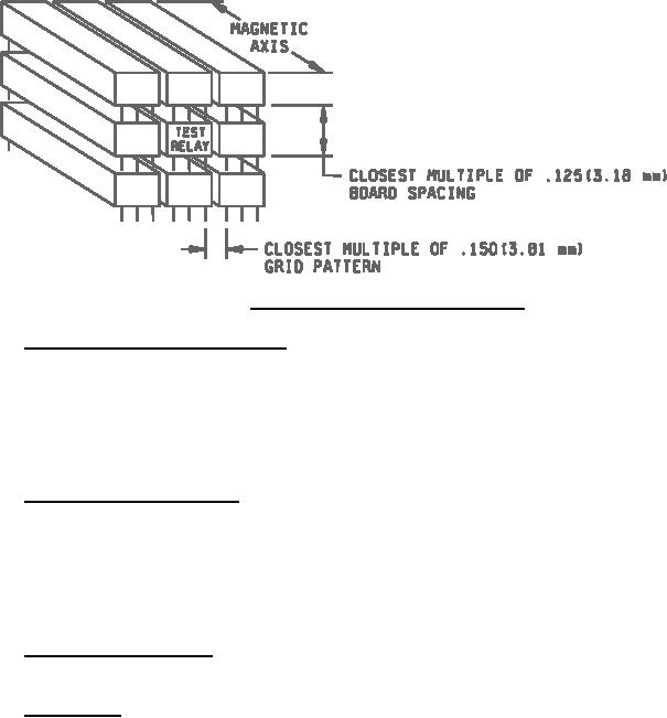
FIGURE 4. Mounting array for adjacent similar relays.
4.5.19 Resistance to soldering heat (see 3.22). Relays shall be tested in accordance with method 210 of
MIL-STD-202. The following details and exceptions apply:
a. Depth of immersion in molten solder: Within .060 .020 inch of the relay base.
b. Test condition: B.
c. Measurements after test: Insulation resistance, contact resistance, pickup and dropout voltage, and dc coil
resistance shall be measured as specified in 4.5.4, 4.5.8, 4.5.6, and 4.5.5, respectively.
4.5.20 Salt spray (corrosion) (see 3.23). Relays shall be tested in accordance with method 101 of MIL-STD-202.
The following details and exceptions apply:
a. Applicable salt solution: 5 percent.
b. Test condition: B.
c. Examination after test: Relays shall be examined for evidence of peeling, chipping, flaking of the finish, and
exposure of base material due to corrosion.
4.5.21 Terminal strength (see 3.24). Relays shall be tested in accordance with test condition A, method 211,
MIL-STD-202. The force shall be as specified (see 3.1) and only two terminals per relay shall be tested.
4.5.22 Life (see 3.25). Each sample relay shall be life tested for a minimum of 50 million operations. The
following details apply:
a. Test temperature: Room temperature.
b. Mounting position: During the performance of all the tests specified herein, the relays shall be positioned,
unless otherwise specified (see 3.1), with the long side of the header vertical and with the terminals
horizontal and with the NO and NC terminals at the top.
c. Arc suppression: An external arc suppression circuit shall be electrically connected to each pair of contacts
which make and break during the life test.
d. Energizing voltage: The rated voltage (see 3.1) shall be used to energize the coil.
e. Cycling rate: The cycling rate shall not be less than 40 Hz or more than 80 Hz. "On" and "off" periods shall
be approximately equal.
13
|
|
Privacy Statement - Press Release - Copyright Information. - Contact Us |
