 |
|||
|
Page Title:
Temperature cycling (see 3.28.1). |
|
||
| ||||||||||
|
|  MIL-R-83407B
f. Contact load: The contact load shall be one ampere resistive at an open circuit voltage of 100 V dc, unless
otherwise specified (see 3.1). A load resistor shall be connected between each stationary contact and the
positive terminal of the load power supply. The negative terminal of the load power supply shall be
connected to the movable contact terminal. Unless otherwise specified (see 3.1), a contact protective circuit
consisting of a 0.1 microfarad capacitor connected in series with a 10 ohm resistor shall be connected
across each stationary contact and the respective movable contact. Connect the outer end of the resistor to
the stationary contact terminal and the outer end of the capacitor to the respective movable contact terminal.
Keep the resistor and capacitor leads and the contact power leads as short as practicable. Route the
contact power supply leads as far away from one another as practicable to minimize lead capacitance.
g. Contact monitoring: The contacts shall not be monitored during the actual life cycling.
h. Periodic measurements: Upon completion of each 5 million operations, the life cycling shall be stopped and
the electric power removed from the relays for approximately one hour. Then perform the dc coil resistance,
contact resistance, pickup and dropout voltage, and operate and release time tests as specified in 4.5.5,
4.5.8, 4.5.6, and 4.5.9, respectively. The dielectric withstanding voltage and insulation resistance tests, as
specified in 4.5.3 and 4.5.4, shall also be performed at the end of the life cycling (50 million operations). The
relays shall then be externally examined to verify that no physical damage exists.
4.5.23 Screening (when specified) (see 3.1).
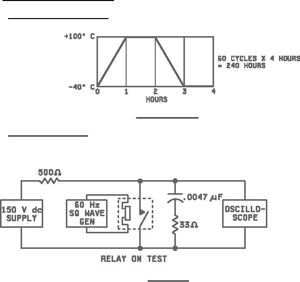
4.5.23.1 Temperature cycling (see 3.28.1). Each relay shall be subjected to 60 temperature cycles.
(60 cycles x 4 hours = 240 hours) (see figure 5).
FIGURE 5. Temperature cycling.
4.5.23.2 ARC duration (see 3.28.2). Each relay shall be subjected to a minimum of 100,000 operations at a rate
of 60 operations per second with 1 ampere resistive load at 24 V dc. Dynamic switching characteristics shall be
tested as shown in figure 6. Observe the oscilloscope for turnoff characteristics and reject any relay that exhibits an
ARC duration greater than specified in 3.28.2.
FIGURE 6. ARC duration.
14
|
|
Privacy Statement - Press Release - Copyright Information. - Contact Us |
