 |
|||
|
Page Title:
Table I. Tension and torque leads for solenoid wire leads, solder lug or hook, stud, or screw, and mounitnd studs |
|
||
| ||||||||||
|
|  MIL-S-4040F
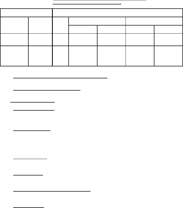
TABLE I. Tension and torque leads for solenoid wire leads, solder lug
or hook, stud, or screw, and mounting studs.
Wire terminals
Threaded terminals or mounting studs
Diameter
Pull tension (lbs)
Torque (inch-pounds)
Pull
(inches)
tension
Size
(lbs)
Terminals
Mounting studs
Terminals
Mounting studs
.035 to .047
4.5
4
5
7
4.4
5
6
30
25
10.0
12
8
35
35
20.0
20
2.0 0.2
Less than .035
10
40
50
32.0
40
.250
50
60
75.0
80
.313
70
80
100.0
160
.375
100
115
150.0
275
3.5.5 Static spring return force (when specified, see 3.1 and 4.7.6). The static spring return force shall fall within
the specific limits.
3.5.6 Magnetic effect (when specified, see 4.7.7). The intensity of the magnetic field surrounding the solenoid
shall not exceed the value specified (see 3.1).
3.6 Environmental requirements.
3.6.1 Thermal shock (see 4.7.8). There shall be no mechanical, electrical, or operational failure, and no cracking,
peeling, or flaking of the finish. During this test, operating force (torque) and deactuating voltage shall be as specified
in 3.5.1.1 and 3.5.1.3, respectively. Following the test, the compensated actuating voltage shall be as specified in
3.5.1.2.
3.6.2 Solderability (see 4.7.9). The critical examination area of solid wire lead and pin terminals shall be at least
95 percent covered with a continuous new solder coating in accordance with method 208 of MIL-STD-202. For
solder-lug terminals greater than .045 inch (1.14 mm) in diameter, 95 percent of the total length of fillet, which is
between the standard wrap wire and the terminal, shall be tangent to the surface of the terminal being tested and
shall be free of pinholes, voids, etc. A ragged or interrupted line at the point of tangency between the fillet and the
terminal under test shall be considered a failure.
3.6.3 Vibration (see 4.7.10). There shall be no evidence of loosening of parts or mechanical damage to the
solenoid. Following this test, the operating force (torque), compensated actuating voltage, and deactuating voltage
(or current) shall be as specified in 3.5.1.1, 3.5.1.2, and 3.5.1.3, respectively.
3.6.4 Shock (see 4.7.11). There shall be no evidence of mechanical or electrical damage, nor shall the test impair
the normal operation of the solenoid. Following this test, the operating force (torque), compensated actuating
voltage, and deactuating voltage (or current) shall be as specified in 3.5.1.1, 3.5.1.2, and 3.5.1.3, respectively.
3.6.5 Acceleration (when specified, see 3.1 and 4.7.12). The solenoids shall meet the specified requirements.
During this test, the compensated actuated voltage and deactuating voltage (or current) shall be as specified in
3.5.1.2 and 3.5.1.3.
3.6.6 Moisture resistance. Unless otherwise specified (see 3.1), solenoids shall be tested in accordance with
4.7.13. There shall be no evidence of breaking, cracking, or spalling of the solenoids. Immediately after step 6 of the
final cycle, the insulation resistance shall be at least 1 megohm, and the compensated actuated voltage shall be as
specified in 3.5.1.2. After the 24 hour drying period, the insulation resistance shall be at least 50 megohms. The
operating force (torque), compensated actuating voltage, and deactuating voltage (or current) shall be as specified in
3.5.1.1, 3.5.1.2, and 3.5.1.3, respectively.
5
|
|
Privacy Statement - Press Release - Copyright Information. - Contact Us |
