 |
|||
|
|
|||
| ||||||||||
|
|  MIL-T-21369C(OS)
3.3.3.7.2 Resistor R14. With the Panel-Chassis Assembly, Drawing 1362835 removed from the
test set case and not energized, the TEST SELECTOR switch at the OFF position and the 5 Meg-
50 Meg switch at the 50 Meg position the resistance between the chassis and the negative (-) test
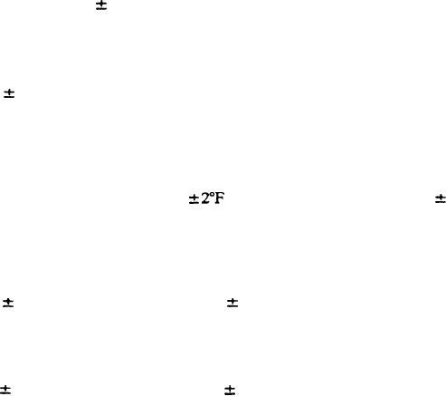
jack, P7, shall be 0.1 megohm 1 percent.
3.3.3.7.3 Resistor R15. With the Panel-Chassis Assembly removed from the test set ease and
not energized, the TEST SELECTOR switch at the OFF position and the 5 Meg-50 Meg switch
at the 5 Meg position the resistance between the chassis and the negative (-) test jack P7, shall
be 10,000 ohms 1 percent
3.3.4 Insulation resistance.
33.4.1 Conditioning. The requirements of 3.3.4.2 and 33.4.3 shall be successfully met at a
relative humidity of 60 percent or more within one-half hour after the test set has been conditioned
and a relative humidity of 75 5 percent.
for at least 24 hours at a temperature of 77
3.3.4.2 500 megohms. With the wipers of the self controlled rotary switch, REL-X at the
HOME position, the TEST SELECTOR at the OFF position, the NO-LOAD-LOAD switch at the
NO LOAD position and Cable Assembly CA-731 disconnected from the power source the
resistance between each pair of points listed by table V (see 4.5.2.7.2g) shall be 500 megohms or
more, when 500 50 volts D.C. is applied for 60 5 seconds.
33.43 50 Megohms. With the wipers of RE-X and the test set switches at the positions
specified by 3.3.4.2 and with Cable Assembly CA-731 disconnected from the power source, the
resistance between each pair of points listed by table VI (see 4.5.2.7.2h) shall be 50 megohms or
more when 500 50 volts D.C. is applied for 60 5 seconds.
3.3.4.4 Cable assembly CA-802. The insulation resistance of Cable Assembly CA-802 shall be
as specified on Drawing 893800.
3.3.5 Operation of the self controlled rotary switch REL-X The self controlled switch
REL-X shall operate as required by the applicable quality conformance tests of 4.5.2. Operation
of the self controlled rotary switch is indicated by the HOME lamp and pilot lamp PL 1 through
PL 11 lighting when required.
3.3.6 Continuity test switch operation. Pilot Lamp PL 14 shall light and be extinguished as
--
required when performing the tests of 4.5.2.8
3.3.7 Test circuits operation. Pilot Lamp PL 12 shall light and be extinguished as required
when performing the test of 4-5.2.9.
3.3.8 Fuse F1. There shall be continuity through Fuse F1 as evidenced by pilot lamp PL 15
lighting when the ON-OFF switch is set at ON and remaining lit for the entire period the ON-
OFF switch remains at ON (see 3.3.3.6.1).
5
|
|
Privacy Statement - Press Release - Copyright Information. - Contact Us |