 |
|||
|
Page Title:
Table II. Conditioning temperature |
|
||
| ||||||||||
|
|  MIL-T-46692B
4.2.3.3.1 Ballistics. Twenty-one units shall be tested to determine compliance with 3.7.
The units shall be temperature conditioned as provided in table II and 4.3.4.2. Failure of any
unit to comply with 3.7.1 through 3.7.9 shall be cause for rejection of the lot.
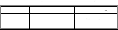
TABLE II. Conditioning temperature.
Sample size
Method
Temperature ( F)
7
Load (see 3.7.1)
65 to 70
7
Load (see 3.7.1)
65 to 75
7
Load (see 3.7.1)
195 to 205
4.2.3.3.2 Retest. There shall be no retests.
4.2.3.3.3 Test failure. If a test failure is attributable to an assignable cause, excluding
the test thruster, the original test results shall be discarded and that test reconducted.
4.3 Test methods and procedures.
4.3.1 Breakaway torque. A torque wrench, set at the torque requirements specified in table
I, shall be used with an appropriate adapter to determine the adequacy of the joint. The cylinder
shall be held secure and the torque shall be applied to the head.
4.3.2 Residual magnetism. The assembly shall be tested for excessive residual magnetism
using an approved compass in an area free of local magnetic effects by placing the assembly 5
inches from the end at the same height as the compass, in the north-south horizontal position (head
end at south) with the compass set in an east-west heading. The assembly shall be moved at a speed
no greater than 10 feet per minute past the compass for its entire length, rotated 90 degrees in
the horizontal position about its longitudinal axis, and moved slowly back past the compass. This
procedure shall be repeated for each 90 degree rotation of the assembly for four full passes.
4.3.3 Radiographic examination. All assembled thrusters shall be radiographically examined
in accordance with MIL-STD-453, with the exception that an thruster assembly will be used for the
penetrameter. Any observable imperfections in components or assembly shall be cause for
rejection. The thrusters shall be positioned for the most revealing exposure, with the long axis
of each assembly perpendicular to the rays of the X-ray machine. All thrusters shall be identified
with serial numbers prior to X-ray examination. The serial numbers shall be in consecutive order
beginning with the number 001 in each production lot. Any missing numbers are to be identified on
the X-rays. The thrusters shall be arranged on trays or boards in consecutive numerical order,
and each radiograph shall carry a permanent identification of the units displayed thereon. The
radiographic plate identification shall include item nomenclature, the complete lot number, the
span of serial numbers displayed, and the contract number. The radiographs of the entire
production lot shall accompany the ballistic sample to the activity conducting the production lot
acceptance test. Defective thrusters found during X-ray review are to be marked on the X-ray prior
8
|
|
Privacy Statement - Press Release - Copyright Information. - Contact Us |
