 |
|||
|
|
|||
| ||||||||||
|
|  MIL-T-81290(WP)
TABLE 3
DMma READOUT TIMES
Mk 363 Timer Readings
Set-in Volts DC
1.00
0,100 seconds
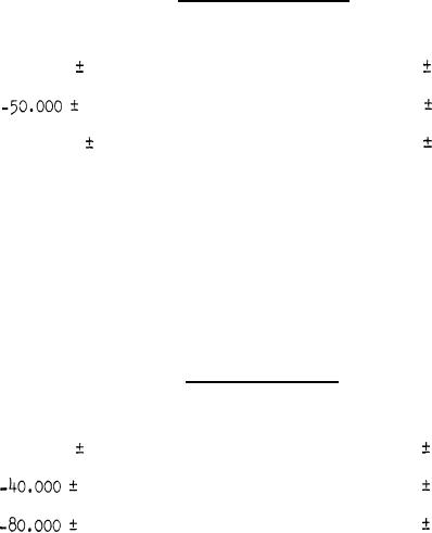
.25.000
0.025
2.00
0.200 seconds
0.050
0.400 seconds
4.00
0.100
-100.000
3.3.10.2 T4 Readout Timing. With 28 plus or minus 3 volts DC applied
across pins k (+) and h (-) and 12.750 plus or minus 0.250 volts DC across
pins S (+) and T(-) of connector P3; with FUNCTION SELECTOR in START, MOTOR
START-BATTERY START in MOTOR START, and with DMma-OFF-T4 in T4 position, T4
readout times shall be as shown in Table 4, after the sequence of voltages
as specified in 3.3.10.1 (a.) through (d.), except that in step (a.) the pre-
saturation and set-in voltages shall be applied through pins C (+) and W (-)
of connector P3.
TABLE 4
T4 READOUT TIMES
Mk 363 Timer Readings
Set-in Volts DC
1.000 seconds
10.00
0.020
-200000
0.040
20.00
2.000 seconds
40.00
4.000 seconds
0.080
3.3.11 Range and Airframe Separation Simulation
3.3.11.1 Operating Voltages. With 12.750 plus or minus 0.250 volts
DC applied across pins S (+) and T (-) of connector P3, the following voltages
shall be present at the designated pins of connector P3:
a. 12.750 plus or minus 0.250 volts DC between pins A (+) and
V (-).
10.000 plus or minus 0.010 volts DC between pins d (+) and
b.
T (-)
c. 2.500 plus or minus 0.010 volts DC between pins B (+) and
T (-)"
8
|
|
Privacy Statement - Press Release - Copyright Information. - Contact Us |