 |
|||
|
Page Title:
Converter, Signal Data CV-2950( )/AWG-9 and CV-3225( )/AWG-9 |
|
||
| ||||||||||
|
|  MI L- T-81785C (AS)
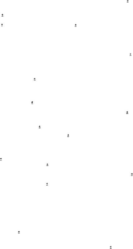
(1) Measure the discriminator zero to an accuracy of
0.05
V in the region of zero volts.
(2) Measure the tracker test frequency to an accuracy of
500 Hz in the region of 7 MHz.
(3) Measure the second integrator output to an accuracy of
5 percent in the region of
10 V [track mode).
Tracking sensitivity (acquisition mode operation).
j.
(1) Verify speed gate positioning by computer simulation.
(2) Measure the signal-to-noise ratio (S/N) for 50 percent
fast frequency on-target (FFOT) to an accuracy of 3
dB.
k.
Accelerating target tracking (tracking mode operation).
Verify accelerating target tracking at various "G" levels
1 "G".
to an accuracy of
l.
Polar error
(1) At the modulating frequencies, measure the polar error
phase shift with continuous wave (CW) carrier to an
5 percent.
accuracy of
(2) At the modulating frequencies, measure the polar error
5
phase shift with noise carrier to an accuracy of
percent.
(3) Verify 4 phase potentiometer settings equivalent to
phase shift to
1 percent.
(4) Measure polar error amplitude with 50 percent modulated
carrier to an accuracy of
5 percent.
m.
Range rate outputs
(1) Measure the target doppler RF output to an accuracy of
2 kHz in the region of 7.2 MHz and measure the amplitude
to an accuracy of
6 mV rms in the region of 70 to 200
mV rms.
(2) Measure the VCO frequency output to an accuracy of
2
kHz in the region of 300 kHz, and measure the amplitude
0.2 V rms in the region of O to
to an accuracy of
s v rms.
(3) Verify switching logic states.
On-target (OT) filters
n.
(1) Verify three OT filter states (FFOT).
(2) Verify BIT VCO slew operation.
BIT Log output. Verify BIT log input versus output to an
o.
5 percent.
accuracy of
Speed tracker logic tests.
p.
(1) Measure false slam rate to an accuracy of
1 false
alarm per second.
-15-
|
|
Privacy Statement - Press Release - Copyright Information. - Contact Us |