 |
|||
|
Page Title:
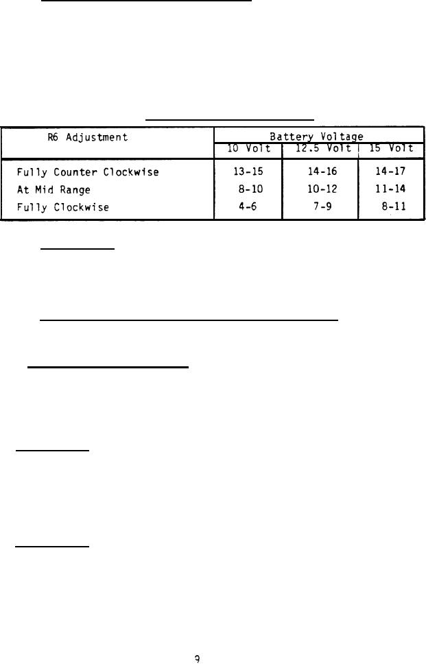
Table I. Number of flashes per sweep. |
|
||
| ||||||||||
|
|  MIL-T-85395(AS)
3.5.1.2.3.1 Sweep circuit and detector circuit. When S2 is depressed, the
sweep voltage shall be generated and applied to the input of the detector
circuit, excluding the detector diode. The sweep voltage shall activate the
detector circuit and cause indicator lamp DS 1 to flash with a period of 1
.5 second and duty cycle of 10 to 25 percent during a portion of the active
The number of flashes per sweep period shall be a function of the
sweep.
adjustment of R6, the battery voltage, and sweep rate and sensitivity varia-
tion. The number of flashes per sweep shall be as specified in table I.
,
TABLE 1.
Number of flashes per sweep.
When S1 and/or S2 is (are) depressed, the DS-2
3.5.1.2.3.2 Battery test.
indicator lamp shall
lash with a period of 2 1 seconds and duty cycle of 10
to 25 percent when the battery voltage is in the range of 10.15 .15 volts dc
It shall not flash when the battery voltage is 10 volts dc or
to 15 volts dc.
less.
3.5.1.2.3.3 Battery condition indicator threshold adjustment. Adjustment of
variable resistor, R12, shall provide a battery condition indicator threshold
range of at least 10 to 10.3 volts.
3.5.1.2.4 Battery charging subsystem.
The electronics assembly shall contain
battery charging capability. A 220 10 volt, 50 10 Hz power source shall
be connected to the test set at connector J101 via the battery charging cable.
The test set shall provide a 7.7 .80 volt peak half sine wave across a 51
ohm resistor connected across J2 pins 7 and 4 or pins 14 and 11.
Pins 14 and
7 shall be positive with respect to pins 11 and 4.
3.5.1.3 Plain shroud. The plain shroud shall be easily attachable/
detachable to/from the electronics assembly. It shall be manufactured in
accordance with drawing 887AS400. The shroud shall provide protection for the
detector subsystem in the electronics assembly from high level electromagnetic
fields and shall absorb and attenuate RF energy radiated from the antenna on
the unit under test. The shroud shall provide at least 4 db attenuation of
the RF signal which is radiated from the weapon during a weapon test.
The EMCON shroud shall be easily attachable!
3.5.1.4 EMCON shroud.
detachable to/from the electronics assembly.
It shall be manufactured in
accordance with drawing 887AS500. The shroud shall provide at least 48 db
attenuation of the RF signal radiated from the weapon during a weapon test.
The EMCON shroud shall be similar to the plain shroud except it shall have the
following additional features:
|
|
Privacy Statement - Press Release - Copyright Information. - Contact Us |
