 |
|||
|
Page Title:
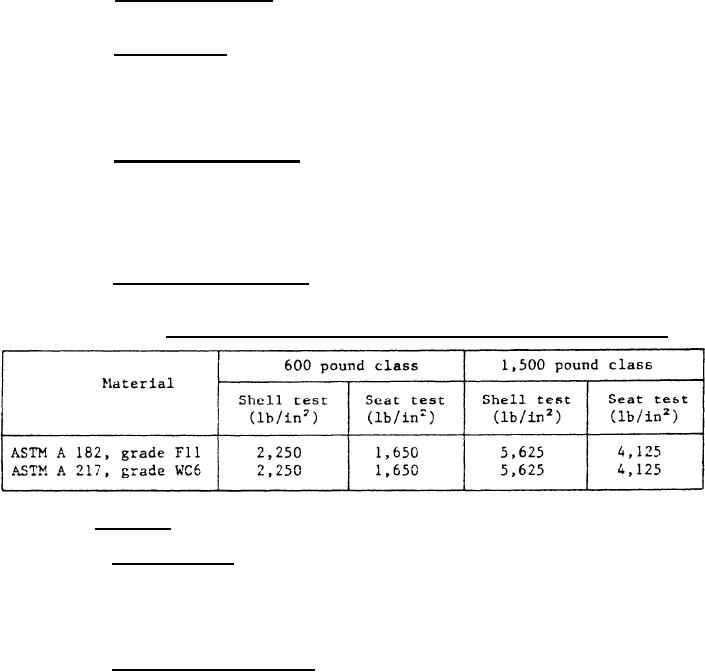
Table III. Hydrostatic tests for shell strength and seat tightness |
|
||
| ||||||||||
|
|  MIL-V-24642(SH)
3.5.3 External leakage. There shall be no visible external leakage during
the seat tightness test of 4.6.6.
3.5.4 Manual trip. The solenoid shall be capable of being manually
tripped, thereby causing the valve to close, regardless of the position of
the disc. Manual trip shall be located so that it is readily accessible to the
person at the trip valve, but cannot be tripped accidentally. A guard shall
be installed around the trip button, lever, or handle.
3.5.5 Shock and vibration. Valves shall meet the shock requirements
for grade A, class 1 of MIL-S-901, and the type I environmental vibration
requirements of MIL-STD-167-1 (including the solenoid). This shall apply to
the entire valve. The valve shall not inadvertently trip as a result of these
conditions. During and subsequent to these conditions, the valve shall perform
its principle function as specified in 3.2.
3.5.6 Hydrostatic pressure. The valve shall pass the test of 4.6.5.
The hydrostatic pressure shall be as specified in table III.
TABLE III.
Hydrostatic tests for shell strength and seat tightness.
3.6 Marking.
3.6.1 Body marking. The manufacturer's name or trademark and the
material composition shall be cast or forged integral with the valve body
and bonnet. The size, rating, and a flat arrow or "inlet" and "outlet"
shall be cast or forged integral with the valve body. Bridge wall markings
shall be cast or forged into the valve body.
3.6.2 Identification plates. Valves shall have an identification plate
made of corrosion-resisting steel or brass. Identification plates shall be
permanently fastened to a part of the valve not subjected to working pressure
and which will not be covered by insulation. Identification plates shall
contain the following data or a space therefore:
(a)
Manufacturer's name.
(b)
MIL-V-24642.
(c)
Body material composition.
(d)
Size and rating.
(e)
maximum inlet temperature and pressure rating.
(f)
Manufacturer's model and part number or identification.
(g)
Manufacturer's drawing numbers.
(h)
Space for 9-digit CID/APL number.
10
|
|
Privacy Statement - Press Release - Copyright Information. - Contact Us |
