 |
|||
|
Page Title:
Figure 2. Brake port and reservoir port proof pressure test |
|
||
| ||||||||||
|
|  MIL-V-5525C
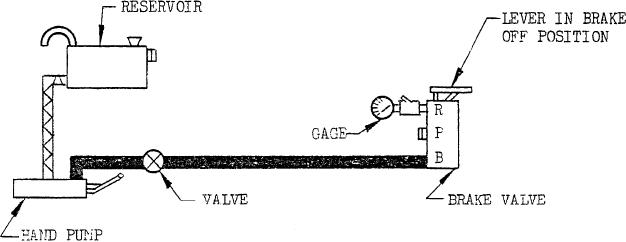
FIGURE 2. Brake port and reservoir port proof pressure test
sure, as specified in 3.3, applied at the brake
acts against a spring-loaded piston.
When fluid displacement specified
port and return port without external leakage
herein has been reached, the pis-
or other malfunctioning. Typical proof pres-
ton will rest against, a stop. The
sure test setups are shown on figure 2. The
simulated brake shall have, as
specified test. pressure shall be applied at the
nearly as possible, the loadstroke
inlet port, bake port, and return port at least
characteristic of the brake used in
2 successive times at each port and held for 2
the system for which the valve is
minutes from the time full pressure is applied.
being tested.
There shall be no external leakage, permanent
set, or failure of the valve assembly.
4.7.2.3 Output pressure and load. With the
brake port connected to a pressure gage and
4.7.4 Burst pressure. The power brake valve
3,000 psi applied to the pressure port, the
shall not fail when subjected to a pressure of
7,500 psi applied at the inlet port with return
brake valve shall be actuated to obtain 100
percent of plunger travel or as specified in
and brake ports open. With the inlet and re-
the applicable specification control drawing.
turn ports plugged, 2.5 times the operating
Brake pressure and plunger load shall `be with-
pressure shall be applied to the brake port.
in the limits specified for the valve on the de-
There shall be no rupture of the valve assem-
bly or internal parts.
sired performance curve or on the accepted
performance of protype units. With the
4.7.5 Leakage. When a single unit or one-
brake part connected to return through a flow-
half of a duplex unit is tested as specified be-
meter and a metering valve, the valve shall be
set in order that at maximum brake pressure
low, the average leakage for the last 4 minutes
rated flow occurs; then the lever shall be oper-
of a 5-minute period shall not exceed that spe-
ated smoothly from maximum pressure to zero
cified on applicable drawings. For this test,
pressure and return several times. The flow
the valve shall be placed in such a position
shall follow the variation in lever position
that the worst and most evident condition of
smoothly with maximum variations in smooth-
leakage occurs.
ness not exceeding 10 percent.
4.7.5.1 With the valve in the brake-off posi-
4.7.3 Proof pressure. The power brake
tion, leakage shall be measured at the brake
valve shall withstand a proof pressure of 4,500
port and return port with 3,000 psi applied
the inlet port. The test setup should be in ac-
psi applied at inlet port and shall withstand a
proof pressure of 1.5 times the operating pres-
cordance with figure 3.
5
|
|
Privacy Statement - Press Release - Copyright Information. - Contact Us |
