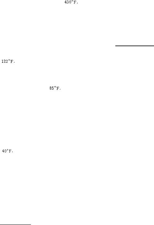
 |
|||
|
|
|||
| ||||||||||
|
|  MIL-C-18419B(SHIPS)
3.3.2- Each compressor shall be capable of con-
passing the type A, class HI (high-impact) shock
tinuously supplying the specified quantity of air at
test specified in MIL-S-901. Grade III equipment
the normal discharge pressures (see 1. 2) and
in accordance with MIL-S-901 is required.
standard design conditions (see 3.3. 4). All com-
NAVSHIPS 250-660-30 may be used as a guide for
pressors shall be capable of satisfactory operation
design of shock resistant Naval equipment.
at an overload pressure of 500 pounds per square
inch (p. s. i. ) over their rated discharge pressure
3. 3.5.2 Shockmounts are not to be used unless
for a period of 2 hours in any 4-hour period.
bureau or agency approval of the mount and its
proposed application is given.
3. 3.3 The temperature of air discharged from
any stage of compression shall not exceed
3. 3.5.3 Bolts designed to be stressed in shear
under standard design conditions and overload dis-
shall be installed in holes with a minimum of
charge pressure conditions. The temperature `
clearance. Hole diameters shall be no more than
shall be measured by temperature sensing devices
1/32 inch larger than the bolts up to 3/4 inch size,
(see 3.3.22.3. 1) located in the air stream as close
and no more than 1 '16 inch larger than bolts of
as physically practicable to the discharge side of
greater than 3/4 inch size. Mounting bolts for
fastening the equipment shall conform to grade 2
the discharge valves.
of MIL-B-857.
3. 3.4 Unless otherwise specified in the contract
3. 3.6 Noise and vibration. -
or order the following standard design conditions
shall be assumed:
3. 3.6.1 Each complete compressor unit in -
cluding the motor, shall be designed to obtain the
(a) Ambient and intake air temperature -
quietest possible operation consistent with com -
(b) Intake air pressure - 14.7 p.s. i. a.
pressor reliability, and accessibility for mainte-
(c) Relative humidity -50 percent.
nance and repair. Equipment shall be designed to
(d) Maximum permissible temperature of air
meet the noise and vibration requirements for grade
leaving the aftercooler - 125 F.
C equipment in MIL-E-22843. `
(e) Temperature of cooling water at inlet -
3.3. 6.2 When specified (see 6. 1) the manufac-
95 F. for submarines;
for surface
ships.
turer shall provide means for supporting the com-
(f) Cooling medium - fresh water on sub-
pressor on Navy furnished sound isolation mounts
designed to Drawing 5000 -S1112-1385778. The
marines, and sea (salt) water on surface
ships.
support mounting shall be on a plane through the
approximate center of gravity of the complete
equipment. Such support mounting shall be inte-
3. 3.4.1 Standard design conditions specified in
gral with the subbase or other compressor support-
3. 3.4 are the conditions under which the compres -
sors shall deliver their rated capacity and pressure.
ing structures. This arrangement shall be clearly
delineated on the drawings. The compressor manu-
The compressors shall also operate satisfactorily
facturer will not be required to furnish any mount -
under the following conditions encountered on ship-
ing members between the isolation mounts and the
board, but not nessarily at rated capacity:
ship's structure,
(a) Minimum ambient and intake temperature -
3. 3.7 Gage board temperature indicating and
alarm instrument, drain valves and all features of
(b) Air intake pressure - 11.7 p.s. i. a. mini-
an operational nature shall be located on and oper-
mum to 18. 7 p.s. i.a. maximum.
(c) Relative humidity - 100 percent at 122 F.
able from one side, designated as the operating
side of the compressor, so as to be accessible if
the compressor is installed adjacent to a bulkhead.
3.3.4. 1.1 The range of air intake pressures
Means shall be provided for the installing activity
(see 3.3.4. l(b)) is applicable for submarine applica-
tions only, and the high intake pressure is not ex-
to relocate, to the opposite side of the compressor,
the gage board with its instruments, and the drain
pected at the same time as the minimum ambient
valves, with only minor rearrangements of wiring
and intake temperature. The motor horsepower
and tubing, in order to facilitate either "right hand"
(hp. ) rating shall be based on an intermittent duty
of 2 hours with an intake pressure of 18.7 p.s.i.a.
or "left hand" installation. This provision shall be
clearly delineated on the drawings.
and intake temperature of 70 F. followed by con-
tinuous duty with intake pressure of 17.7 p.s.i.a.
3. 3.8 The crankcase, frame, housing, cylin-
and intake temperature of 70" F.
ders, and other fixed parts or attached component
3. 3.5 Shockproof ness. -
parts of the assembly shall be rigidly secured and
held in alignment by dowel pins, fitted bolts, keys,
3. 3.5.1 The design of all complete air com-
pressor units shall be such that they are capable of
4
|
|
Privacy Statement - Press Release - Copyright Information. - Contact Us |