 |
|||
|
Page Title:
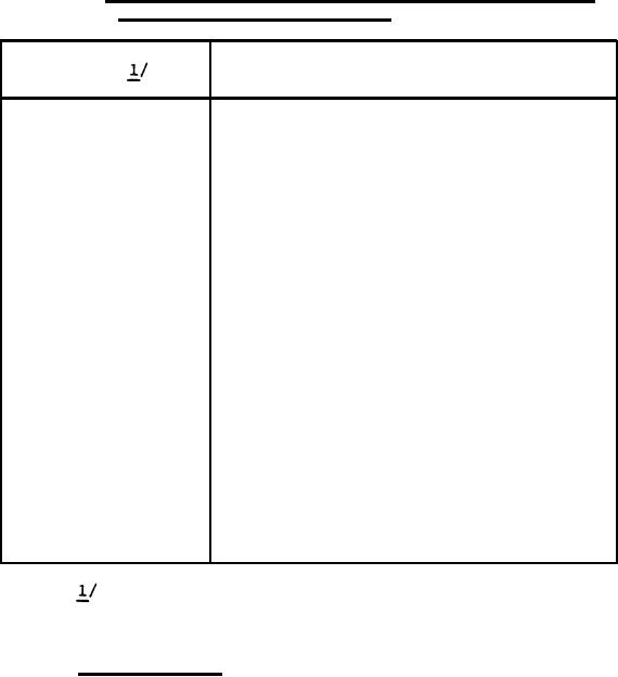
Table 1. SBK-11A/A24G-26 Displacement Gyroscope Connector to Electronic Control Amplifier |
|
||
| ||||||||||
|
|  MIL-C-38418E(AS)
TABLE 1.
SBK-11A/A24G-26 Displacement Gyroscope Connector to
Electronic Control Amplifier
Function
Pins
Heading output, A excited
1 (S1)
2 (S2)
Heading output, A excited
3 (S3)
Heading output, A excited
4
Erection warning
5
Pitch erection
Roll erection
6
7
Test Connection, 26V C
8
Fast erection excitation, 78V C
9
Lateral acceleration sensor
Pitch output, A excited
10 (S1)
Pitch output, A excited
11 (S2)
Pitch output, A excited
12 (S3)
Pitch output, A excited
13 (S1)
Pitch output, A excited
14 (S2)
Pitch output, A excited
15 (S3)
16
Linear acceleration sensor
N. Latitude control and slaving
17
18
S. Latitude control and slaving
19
S pare
20
Spare
21`
Ground - neutral
22
115V A
23
115V B
24
115V C
Connector (1J1) MS24264R16B24PNX to mate with
MS24266R16B24SN
3.6.6
Vertical Drift - The vertical gyro assembly shall be so
designed that the maximum free drift, noted after compensation for the
earth's rotation, shall be not greater than 0.200 per minute under
standard conditions and 0.25 per minute over the temperature range
specified in 3.9.
11
|
|
Privacy Statement - Press Release - Copyright Information. - Contact Us |