 |
|||
|
|
|||
| ||||||||||
|
|  MIL-C-62204B(AR)
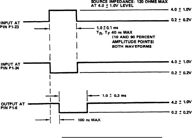
3.3.6 Test range signal. With the digital type-A signals (item 3.1 of
table I) applied between pins P1-23 and P1-7 and pins P1-24 and P1-7 as speci-
fied on figure 5, the output between pins P1-6 and P1-7 shall be as specified
on figure 5. (See 4.6.2.6)
FIGURE 5. Test range input and output signal waveforms.
3.3.7 Reticle light signals. With the 300 ohm loads (item 1.1 of table
I) connected as specified therein, and with the logical zero digital type-A
signal (item 3.1 of table I) applied between pins P2-24 and P1-7, the output
voltages between pins P2-22 and P1-7 and pins P2-23 and P1-7 shall be 0.2
0.2V. With the 15 Vdc signal (item 3.5 of table I) applied between pins
P2-24 and P1-7, the voltages between pins P2-22 and P1-7 and pins P2-23 and
P1-7 shall be 12 2.0V. (See 4.6.2.7)
10
|
|
Privacy Statement - Press Release - Copyright Information. - Contact Us |
