 |
|||
|
Page Title:
Table II. Conditioning temperature. |
|
||
| ||||||||||
|
|  MIL-I-60284B
4.2.3.4 Initiator pin security. The initiator pin of each subassembly shall be subjected to
the initiator pin security test. Failure of any unit to comply with the requirements of 3.6 shall
be cause for rejection of the subassembly.
4.2.3.5 Functional tests. The following tests shall be performed by the Government.
4.2.3.5.1 Ballistics. Twenty-one units shall be tested to determine compliance with 3.8.
The units shall be temperature conditioned as provided in table II and 4.3.6.2. Failure of any
unit to comply with 3.8 shall be cause for rejection of the lot.
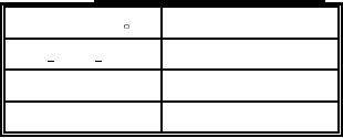
TABLE II. Conditioning temperature.
Temperature ( F)
Sample Size
60 to 70
7
65 to 75
7
195 to 205
7
4.2.3.5.2 Retest. There shall be no retests.
4.2.3.5.3 Test failure. If a test failure is attributable to an assignable cause, excluding
the test initiator, the original test results shall be discarded and that test reconducted.
4.3 Test methods and procedures.
4.3.1 Breakaway torque. The torque wrench set as specified in 3.3 shall be used in conjunction
with a fixture to determine the adequacy of the joints. The chamber shall be secured in an air
vise, and the torque shall be applied to the cap.
4.3.2 Residual magnetism. The assembly shall be tested for excessive residual magnetism
using an approved compass in an area free of local magnetic effects by placing the assembly 5
inches from the end and at the same height as the compass, in the north-south horizontal position
(cap end at south) with the compass set in an east-west heading. The assembly shall be moved at a
speed no greater than 10 feet per minute past the compass for its entire length, rotated 90 degrees
in the horizontal position about its longitudinal axis, and moved slowly back past the compass.
This procedure shall be repeated for each 90 degree rotation of the assembly for four full passes.
4.3.3 Firing pin release. The subassembly shall be secured in the fixture. A pull shall be
applied to the initiator pin in the longitudinal direction in conjunction with the fixture which
registers the amount of pull.
4.3.4 Initiator pin security. The subassembly shall be secured in the fixture with the safety
pin in place. A pull shall be applied to the initiator pin in the longitudinal direction in
conjunction with the fixture which registers the amount of pull. The test shall be performed with
the safety pin in each position.
9
|
|
Privacy Statement - Press Release - Copyright Information. - Contact Us |
