 |
|||
|
Page Title:
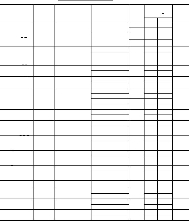
Table 1. Electrical performance characteristics-cont. |
|
||
| ||||||||||
|
|  MIL-M-38510/108A
TABLE I. Electrical performance characteristics Continued.
Temperature
Device
Limits 1/
Unit
Conditions
Test
Symbol
range
type
Min
Max
mV/C
ĆVBE/ĆT
-55C ≤ TA ≤ +25C
Temperature
VCE = 3 V, IE = -1 mA
01
-2.2
-1.5
coefficient of base
02
-2.2
-1.3
emitter voltage
+25C ≤ TA ≤ +125C
01
-2.2
-1.5
5/ 8/
02
-2.2
-1.3
ĆVBE(D)/ĆT
-55C ≤ TA ≤ +25C
mV/C
Temperature
VCE = 3 V, IE = -1 mA
01
-5.0
-3.5
coefficient of base
+25C ≤ TA ≤ +125C
-5.0
-3.5
emitter voltage,
Darlington pair
3/ 8/
(Ć|VBEQA -
-55C ≤ TA ≤ +25C
V/C
VCE = 3 V, IE = -1 mA
Temperature
15
01, 02
VBEQB|)/ĆT
coefficient of input
+25C ≤ TA ≤ +125C
15
offset voltage 5/ 9/
VCE = 3 V, IC = 10 A
+25C ≤ TA ≤ +125C
01, 02
Static forward
hFE
45
current transfer
TA = -55C
25
ratio (beta)
+25C ≤ TA ≤ +125C
01
Static forward
hFE
VCE = 3 V, IC = 1 mA
70
300
current transfer
TA = -55C
40
ratio (beta)
+25C ≤ TA ≤ +125C
02
70
TA = -55C
40
+25C ≤ TA ≤ +125C
01, 02
Static forward
hFE
VCE = 3 V, IC = 10 mA
60
current transfer
TA = -55C
35
ratio (beta)
TA = +25C
Magnitude of static
hFEQA/hFEQB
VCE = 3 V, IC = 1 mA
01, 02
0.9
1.1
beta ratio for any
-55C ≤ TA ≤ +125C
0.85
1.15
two isolated
transistors 5/ 6/ 7/
+25C ≤ TA ≤ +125C
hFE(D)
01
Static forward
VCE = 3 V, IC = 1 mA
4000
current transfer
TA = -55C
2500
ratio, Darlington
pair 3/
+25C ≤ TA ≤ +125C
01
Static forward
hFE(D)
VCE = 3 V, IC = 100
2500
A
current transfer
TA = -55C
1500
ratio, Darlington
pair 3/
TA = -55C
01, 02
Low frequency,
VCE = 3 V, IC = 1 mA
35
hfe
small signal,
+25C ≤ TA ≤ +125C
60
forward current
transfer ratio
TA = +25C
Gain-bandwidth
See figure 4
01, 02
300
MHz
ft
product
TA = +25C
01, 02
ns
Delay time
See figure 2
100
td
TA = -55C, +125C
160
TA = +25C
01, 02
ns
See figure 2
50
Rise time
tr
TA = -55C, +125C
80
TA = +25C
01, 02
ns
See figure 2
200
Storage time
ts
TA = -55C, +125C
300
See footnotes at end of table.
5
|
|
Privacy Statement - Press Release - Copyright Information. - Contact Us |