 |
|||
|
Page Title:
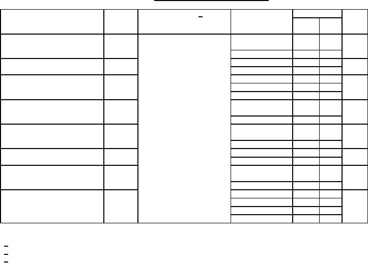
Table 1. Electrical performance characteristics-cont. |
|
||
| ||||||||||
|
|  MIL-M-38510/231C
TABLE I. Electrical performance characteristics.
Units
Limits
Test
Symbol
Conditions 1/
Device
-55C ≤ TC ≤ +125C
Type
Min
Max
unless otherwise specified
Data setup time prior to write
tDCWL
VCC = 4.5 V and 5.5 V
01, 02, 05, 06-
5
ns
CL = 30 pF
12, 14, 15
See figure 5
03, 04, 13
10
Data hold time after write
tWHDC
01, 02, 05-15
5
ns
03, 04
10
Address setup time prior to
tAVWL
01, 02
15
ns
write
03-06, 09-13, 15
10
07, 08, 14
5
Address hold time after write
tWHAC
01, 02, 07, 08,
5
ns
13, 14, 15
03-06, 09-12
10
Chip select setup time prior to
tSVWL
01, 02, 05-12,
5
ns
write
14, 15
03, 04, 13
10
Chip select hold time after
tWHSC
01, 02, 05-15
5
ns
write
03, 04
10
Write enable time to high
tWLQZ
02, 04, 06, 10,
45
ns
impedence
12,13, 14, 15
08
35
ns
Chip select disable time to
tSCQZ
01, 05, 02, 04, 06
50
high impedance
07, 08, 13, 14
35
09, 10, 11, 12
45
15
40
1/ Complete terminal conditions shall be specified in table III.
2/ Not more than one output shall be shorted at one time.
3/ ICC is measured with all inputs grounded for device types 01-08 and 13; and all inputs and outputs open for
device types 09-12, 14, and 15.
5
|
|
Privacy Statement - Press Release - Copyright Information. - Contact Us |
