 |
|||
|
|
|||
| ||||||||||
|
|  MIL-R-48595A(AR)
c. One of the MODE lamps shall illuminate and correspond to the
position of the MODE switch.
d.
The RANGE lamp shall illuminate steady or flash and correspond to
the position of the MODE seleetor switch.
e. With the EMER POWER switch set to the OFF position after the
power turn-on conditions are met, the analog voltage between
J6-D l d J6-L shall be 1.70 0.25 Vrms.
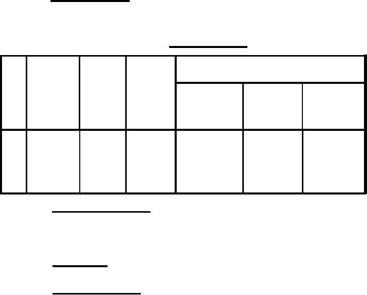
3.3.2 Ranging operation. The RANGE button shall "function in accordance
with requirements specified in table II and in the cyclical numerical sequence
established by the item numbers of that table. (See 4.6.2.2)
TABLE II. Ranging operation.
RESULT
RANGE
RANGE
button
LAST
button
lamp
lamp
PFN
Action
lamp
Button
Item
No change
No change
No change
Pressed
RANGE
1
Steady
Steady
No change
Flashing
2
Steady
RESET
Pressed
out
Discharges
out
RANGE
3
Fleshing
Pressed
NO change
No change
Discharging
4
None
RANGE
out
No change
Charged
Steady
None
5
Steady
RANGE
3.3.3 Range return selector. With the SELECT indicator lamp illuminated
and with buttons 1, 2 and LAST pressed singly in l ny sequence, each range of
not more than the first three target returns shall be displayed singly in the
same sequence. The consecutive button identification shall correspond to the
first, second and third target returns. (See 4.6.2.3)
3.3.4 RESET switch. With the RESET button pressed, the RANGE and RETURNS
readouts shall be zero. (See 4.6.2.4)
3.3.5 BATTLE RANGE switch. With the MODE switch in the ON, TEST, or AUTO
position and with the BATTLE RANGE switch pressed, the 1200 meter range shall
be generated and strobed into the computer, the RANGE end RETURNS readouts
shall be zero and the BATTLE RANGE lamp shall illuminate. The analog voltage
between J6-D and J6-L shall be 1.277 0.10 Vrms. (See 4.6.2.5)
5
|
|
Privacy Statement - Press Release - Copyright Information. - Contact Us |