 |
|||
|
Page Title:
Table VII. Nominal orifice size and disc harge capacity |
|
||
| ||||||||||
|
|  MIL-S-24686A(SH)
Nominal orifice size and disc harge capac i ty .
TABLE II.
Nominal orifice
Discharge
Nominal
size marked
orifice
coefficient
Orifice
on frame
"K"
Pintle"
type
size (in.)
Yes
Yes
1.3 - 1.5
small
1/4
Yes
Yes
small
3/8
2.6 - 2.9
No
1/2
5.3 - 5.8
No
Standard
Yes
7.4 - 8.2
Yes
Large
17/32
*
A stationary pin or rod used to identify non-standard orifice sizes.
I
3.2.4 Inlet threads. The sprinkler body shall be constructed with a 1/2
inch NPT male thread in accordance with ANSI B1.20.1. Threads shall be clean cut
and true, and free from burrs, scoring, or chatter marks.
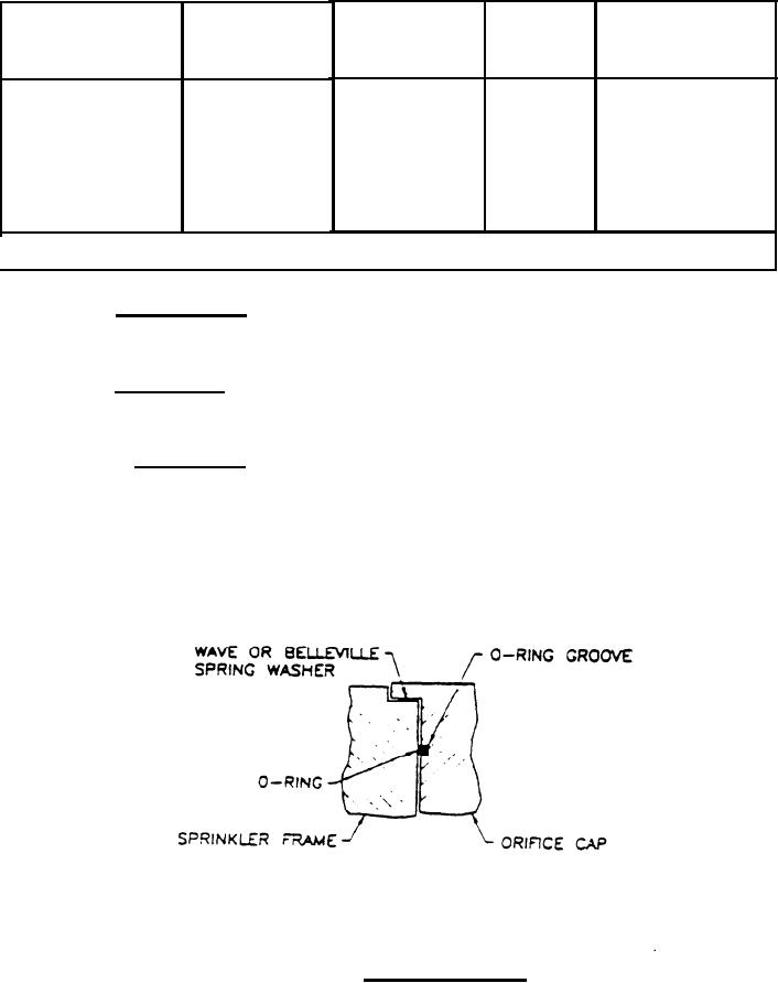
3.2.5 Seal desire. The seal between the orifice cap and the sprinkler body
shall conform to the design described in 3.2.5.1 or 3.2.5.2. No other seal
designs are acceptable.
3.2.5.1 O-Ring seal. The seal shall be provided by a radial O-ring in the
orifice bore. The O-ring shall be captive in the O-ring groove in the orifice
cap . A wave spring, Belleville washer, or similar ejector or spring device shall
be under the shoulder area of the orifice cap, in the counterbore of the sprinkler
frame, as applicable. Any lubricant used on the O-ring shall be compatible with
the O-ring, orifice cap, and sprinkler body in a seawater environment. The basic
design concept is illustrated on figure 1.
O-Ring seal design .
FIGURE 1.
5
|
|
Privacy Statement - Press Release - Copyright Information. - Contact Us |
